Table of Contents
Advertisement
Quick Links
Advertisement
Table of Contents

Related Manuals for ALPHA LITE HORI LIGHT CYC Series


Summary of Contents for ALPHA LITE HORI LIGHT CYC Series
- Page 1 LED LIGHTING FOR UHD BROADCASTING EST.2008 CYC HORI LIGHT CYC SERIES USER MANUAL...
-
Page 2: Safety Information
Safety Information 1. Do not open or disassemble the cover to reduce the risk of electric shock. WARNING 2. Please wear safety equipment such as safety helmet during work. 3. Be sure to fix the safety chain on the product when installing and moving. 4. -
Page 3: Table Of Contents
Contents [LCD Screen Instruction] [Error Information] Safety Information Unlocking Temperature Sensor Contents Screen Instruction Network Connection [Fixture Information] Menu Tree [Extra Information] Fixture Information Main Screen by Mode Color Macro & Product Information Fixture Exterior View Light Distribution DMX Mode Dimensions [Protocols] (Channel Change &... -
Page 4: Fixture Information
Fixture Information Ceiling bridge + Clamp Floor Leg Evenly distributes the horizont over 8m Based on 5 colors of R, G, B, W + Amber, great color presentation from primary color to pastel tone Sturdy and slim type with beautiful exterior design ... -
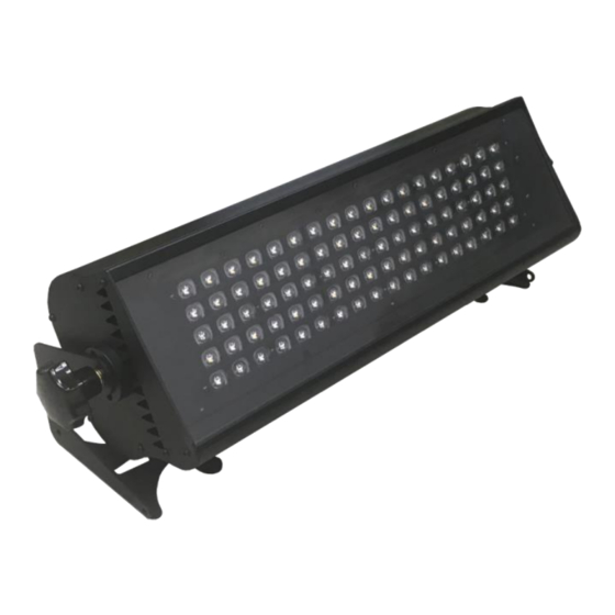
Page 5: Fixture Exterior View
Fixture Exterior View Connector Smart Touch Panel LCD Screen Fixed Knob... -
Page 6: Dimensions
Dimensions (CYC400) (inch) - Page 7 Dimensions (CYC500) (inch)
- Page 8 Dimensions (CYC800) (inch)
-
Page 9: Technical Specifications
Technical Specifications CYC400 CYC500 CYC800 Physical Size 520 x 206 x 176mm 670 x 206 x 176mm 860 x 206 x 176mm LED Chip CREE XP-E 3W 60ea CREE XP-E 3W 90ea CREE XP-E 3W 120ea Beam Angle 60x135° / 85x150° / 130x60° / 20x60° / 30x60° / 40x60° Weight (kg/lbs) 6.5 / 14.3 8.1 / 17.8... -
Page 10: Power Connection
Power Connection AC power at 100-240V, 50-60Hz 1. POWER ON/OFF SWITCH 2. POWER IN 3. POWER OUT 4. DMX IN 5. DMX OUT USB PORT (for ADMINISTRATOR ONLY) (Do not connect USB without administrator's permission.) 1. Observe the proper voltage range 2. -
Page 11: Dmx Connection
DMX Connection 3-pin or 5-pin XLR sockets are equipped for DMX input and output, depending on user needs. Connect the controller to a lighting, or lighting fixture to other lighting fixture. If user uses a standard DMX controller, the DMX output of the controller can connect directly to the DMX input of the first fixture in the DMX chain. -
Page 12: Unlocking
Unlocking Main Screen (Locked) Fixture ID Screen (Locked) When the fixture is turned on, the Smart Touch screen automatically locked. To unlock the touch screen, touch the finger icon( ) three times. If you do not touch for 30 seconds, the lock is reset. -
Page 13: Screen Instruction
Screen Instructions Current Mode Display DMX MODE or USER MODE or COLOR MODE. Current Channel Mode Display current channel mode (only display on DMX MODE) DMX512 Address Display current DMX512 Address. Brightness (Intensity) Displays the brightness value(0~100%) of the equipment. CCT (Correlated Color Temperature) Displays the color temperature(2500~10000K) of the equipment. -
Page 14: Menu Tree
Menu Tree Θ Home (Main screen) Θ DMX512 Mode Θ Setting DMX mode select Sleep mode setup DMX address input Master function setup Θ Information RDM mode setup DMX channel value Dimming speed setup Θ User Mode Θ Information Intensity setup Description of each function Color temperature setup Θ... -
Page 15: Main Screen By Mode & Product Information
Main Screen by Mode & Product Information (DMX MODE) (USER MODE) (COLOR MODE) The current mode is displayed among DMX mode, user mode and color mode(not applicable model) in the upper left corner of the main screen, and the DMX address number of the equipment is displayed in the middle with a yellow number. At the bottom, the current lighting value and fixture temperature are displayed, and some lighting value can be adjusted on the main screen by touching the value. -
Page 16: (Channel Change & Address Setup)
DMX Mode Channel Change & Address Setup - DMX MODE : It is used to adjust by DMX512 signal. User can move to the DMX channel change screen by selecting ‘DMX512 MODE’ button in main screen. In DMX512 MODE screen, user can select DMX channel mode on top tap, and input DMX512 address by pressing the number pad. -
Page 17: User Mode
User Mode Setup & Intensity / CCT Adjust - USER MODE : It is used when the user directly manipulates the equipment. User can move to the User Mode change screen by selecting ‘USER MODE’ button or press ‘Current Intensity’, ‘Current CCT’, ‘Current Tint’ in main screen to activate function control bar. In USER MODE screen, select the bar user want to change to activate(Orange color), and can adjust the activated value by dragging. -
Page 18: Color Mode
Color Mode Setup & RGB / Hue / Saturation / White Adjust - Color Mode : It is used when the user directly manipulates the equipment. User can move to the Color mode change screen by selecting ‘COLOR MODE’ button in main screen. In COLOR MODE screen, select the bar user want to change to activate orange color, and can adjust the activated value by dragging. -
Page 19: Sleep Mode Function
Extra Function – Sleep Mode / Master / RDM / Dimming Speed Additional settings besides the main icons can be setup by selecting SETTING button in main screen. In SETTING, user can set SLEEP MODE, MASTER, RDM, and DIMMING SPEED features. Each time touch the SLEEP MODE, MASTER SETUP, RDM MODE user can select On or Off, and DIMMIN SPEED SETUP can be activated by touching, and press +, - to adjust the value. -
Page 20: Fixture Id Number Setup
Fixture ID & Label Setup (Main Screen) (Fixture ID Screen) (Fixture ID Input window) User can change the screen to Fixture ID and number Pressing the Info button in FIXTURE ID, by selecting FIXTURE ID button in main screen. displays description of the function. In FIXTURE ID, touch the large number to switch to the Fixture ID It is the number value 001 to 9999 for the number(from 1 to 9999) input window. -
Page 21: Error Information
Error Information Temperature Detects the temperature of the current fixture(LED, drive, housing) and displays it on the Smart Touch LCD screen. 45˚C or less is cyan, 46~69˚C is yellow, and 70˚C or more is red. Sensor If the temperature exceeds 75˚C, the actual LED output will decrease. If it exceeds 85˚C, the actual LED output will be 0%, and 'Temperature Error Please Check Device !!' will be displayed. -
Page 22: Color Macro
Color Macro & Light Distribution ■ Color Macro Channel 4 is Color Macro express rainbow gradation effect. The order is Red -> Green -> Blue ■ Distribution 6m(w) x 8m(h) 12m(w) x 8m(h) -
Page 23: Dmx Protocols
DMX Protocols (1/2) Channel Mode Mode Channel DMX Value Function 0-255 0-100 Dimming 0-255 0-100 Color Macro 0-255 0-100 0-255 0-100 Green 0-255 0-100 Blue 0-255 0-100 Amber 0-255 0-100 White 0-255 0-100 Dimming 0-255 0-100 0-255 0-100 Green 0-255 0-100 Blue 0-255... - Page 24 DMX Protocols (2/2) 2 & 9 Channel Mode : Color Macro DMX Value Color Value Color Macro DMX Value Color Value Color Macro DMX Value Color Value Color Macro 1 - 6 3200K 95 - 98 179 - 182 7 - 12 4500K 99 - 102 183 - 186...
-
Page 25: Rdm Protocols
RDM Protocols (1/3) Parameter ID Discovery command SET command GET command DISC_UNIQUE_BRANCH DISC_MUTE DISC_UN_MUTE DEVICE_INFO SUPPORTED_PARAMETERS SOFTWARE_VERSION_LABEL DMX_START_ADDRESS IDENTIFY_DEVICE DEVICE_MODEL_DESCRIPTION MANUFACTURER_LABEL DEVICE_LABEL SENSOR_DEFINITION SENSOR_VALUE DMX_PERSONALITY DMX_PERSONALITY_DESCRIPTION STATUS_MESSAGES Lamp Controls Control Property Value (Example) Description User Settings Remarks Device identification action active Identify On Enable Identify device = Same as On... - Page 26 Description User Setting Remarks Device Model Description CYC500 Model number of the device Disable Manufacturer Label ALPHA LITE Name of the manufacturer Disable Device Label HORI123 ex) Input :HORI123 ►Name : HORI123 Fixture name and management ►Management # : 123...
- Page 27 RDM Protocols (3/3) Sensor Device Sensors Value (Example) Description User Setting Remarks Sensor Temp 64 ˚C Current fixture temperature Disable Error Message Condition Level Description Display Sensor Over Temp Warning Orange message Fixture temperature 46 ~ 69˚C Sensor Over Temp Error Fixture temperature over 70˚C Red message...
Need help?
Do you have a question about the HORI LIGHT CYC Series and is the answer not in the manual?
Questions and answers