
Related Manuals for Taylor ARC4000 Series


Summary of Contents for Taylor ARC4000 Series
- Page 1 TAYLOR STUDWELDING SYSTEMS LIMITED OPERATING GUIDE TYPE 1200E DRAWN ARC CONTROLLER V-21A...
- Page 2 INDEX PAGE No. CONTENT USEFUL INFORMATION. IMPORTANT SAFETY INFORMATION. INTRODUCTION TO STUDWELDING. GUIDE TO EXTERNAL FEATURES. SETTING UP AND WELDING. WELDING TIME AND CURRENT SETTINGS. VISUAL WELD INSPECTION. WELD TESTING. STUDWELDING TECHNIQUES. PARTS LIST & EXPLODED DIAGRAMS. PCB’s - LED GUIDE. CIRCUIT SCHEMATIC.
-
Page 3: Useful Information
USEFUL INFORMATION MANUFACTURERS DETAILS TAYLOR STUDWELDING SYSTEMS LIMITED COMMERCIAL ROAD DEWSBURY WEST YORKSHIRE WF13 2BD ENGLAND TELEPHONE +44 (0)1924 452123 FACSIMILE +44 (0)1924 430059 email sales@taylor-studwelding.com www.taylor-studwelding.com SALES DIRECT TEL +44 (0)1924 487703 TECHNICAL HELPLINE : +44 (0)1924 487701 You may wish to record the details of your controller below as this information will help CONTROLLER SERIAL No. -
Page 4: Further Information
DO NOT USE THIS WELDING POWER SOURCE FOR PIPE THAWING. THIS EQUIPMENT HAS BEEN EMC TESTED AND APPROVED IN ACCORDANCE WITH BS EN 60974-10 (CATEGORY 2). Taylor Studwelding Systems Limited reserves the right to amend the contents of this guide without notification. V-21A... -
Page 5: Important Safety Information
IMPORTANT SAFETY INFORMATION ! PROTECT YOURSELF AND OTHERS ! Read and understand these safety notes. ELECTRICAL No portion of the outer cover of the welding controller should be removed by anyone other than suitably qualified personnel and never whilst mains power is connected. ALWAYS DISCONNECT THE MAINS LEAD BEFORE ATTEMPTING ANY MAINTENANCE. -
Page 6: Limitations Of Use
During welding operations, intense magnetic and electrical fields are unavoidably produced which may interfere with other sensitive Electronic equipment. All Taylor Studwelding equipment is designed, manufactured and tested to conform the current appropriate European standards and directives regarding electromagnetic emissions and immunity and as such is safe to use in any normal environment. -
Page 7: Introduction To Studwelding
INTRODUCTION TO STUDWELDING The Taylor Studwelding 1200E Drawn Arc controller when matched with an appropriate pistol and earth cables is intended for precision stud welding up to 16 mm diameter reduced base studs. The controller is easily transportable and has been designed to operate with a minimum amount of maintenance. -
Page 8: Mains On/Off Switch
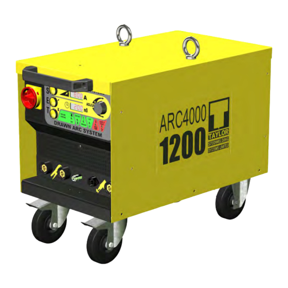
GUIDE TO EXTERNAL FEATURES FRONT PANEL GUIDING HANDLE ! NOT FOR LIFTING ! MAINS ON/OFF SWITCH CONTROL PANEL SEE PAGE 9 SHIELDING GAS OUTLET SOCKET WELDING EARTH CONNECTION SOCKET FRONT CASTOR SWIVEL & BRAKE TYPE VENTILLATION HOLES ! DO NOT OBSTRUCT ! PISTOL CONTROL CONNECTION SOCKET V-21A... - Page 9 GUIDE TO EXTERNAL FEATURES CONTROL PANEL CURRENT SETTING PUSHBUTTON WELDING TIME/GAS PURGE TIME DISPLAY WINDOW WELDING CURRENT DISPLAY WINDOW STUD TO WORK PIECE CONTACT INDICATOR - GREEN PISTOL LIFT COIL ENERGISED INDICATOR - GREEN ADJUSTER KNOB WELDING TIME SETTING PUSHBUTTON GAS PURGE TIME SETTING PUSHBUTTON GAS FLOWING INDICATOR - GREEN PISTOL TRIGGER ACTUATED INDICATOR - GREEN...
- Page 10 GUIDE TO EXTERNAL FEATURES BACK PANEL LIFTING EYEBOLT RATING/SERIAL PLATE VENTILLATION GRILLE ! DO NOT OBSTRUCT ! REAR CASTORS FIXED TYPE. NO BRAKE. SHIELDING GAS INLET SOCKET 3 Ph MAINS CABLE INLET GLAND V-21A...
-
Page 11: Setting Up And Welding
SETTING UP AND WELDING Set up the control unit at the place of work, ensuring that the mains switch is in the OFF position. Plug the controller into a suitable three phase AC supply with a 63A motor rated fuse/breaker. Plug the welding earth cables into the controller. - Page 12 SETTING UP AND WELDING Switch the controller ON by turning the mains switch clockwise through 90°. The ventilation fan will start and the display will illuminate and carry out a start up diagnostic routine taking approx’ 6 seconds. A guide to the recommended time and current settings can be found on page 14 of this guide.
- Page 13 SETTING UP AND WELDING Place the pistol perpendicular to the work piece with the stud touching down at the desired location to be welded. Press down on the pistol until the ceramic ferrule rests firmly on the work piece. Press the trigger to initiate the weld sequence.
- Page 14 WELDING TIME AND CURRENT SETTINGS STUD ACTUAL WELD WELD This page is intended as a guide to setting your TYPE DIAMETER CURRENT TIME machine. (mm) (ms) A set of basic formulae as defined by the British Standard BS EN ISO 14555:2006 (European Standard EN ISO 14555:2006) Annex A.2.7.2.2 and Annex A.2.7.2.4 may be used to calculate the current and time settings to weld any stud.
-
Page 15: Visual Weld Inspection
VISUAL WELD INSPECTION This page will help you to recognise a poor weld when you see one and give some of the possible explanations as to how it may have occurred. Your test welds should look like the first example diagram in the series and once you transfer to the actual job, periodic checks should be made to ensure that your welding is consistently good. - Page 16 WELD TESTING There are two factors which should receive special attention in establishing visually whether or not a stud weld is sound. These are : • The length after weld (L.A.W.) of the stud should be correct. That is to say that a stud which is intended to be 50 mm long after welding, should be correct within +0/-1 mm.
- Page 17 WELD TESTING 2. NON DESTRUCTIVE TESTING. Generally the most practical way of testing threaded stud welds, without destroying the stud, is with the use of proof tests. A torque wrench is particularly useful for this purpose. Below and overleaf are some tables which you may find useful. However, it must be noted that : •...
- Page 18 WELD TESTING Stud loads - Full Base Drawn Arc Studs (kN) Mild Steel Mild Steel Mild Steel Stainless Stainless Stainless Steel Steel Steel Thread Yield Safe Yield Safe M5 x 0.8 M6 x 1.0 10.6 M8 x 1.25 15.2 12.3 19.6 12.7 10.1...
- Page 19 STUDWELDING TECHNIQUES The operating instructions given previously in this guide apply to the majority of general applications where it is possible to use the pistol in the down hand position and with standard cable lengths. For many applications these conditions do not apply and the following notes will give some guidance as to the methods used to obtain satisfactory results for a variety of applications.
- Page 20 STUDWELDING TECHNIQUES 5. WELDING STUDS LESS THAN 25 mm LONG USING FERRULES. As we have seen previously, the stud is held in a recess in the chuck and must be long enough to allow us to set the correct protrusion. A standard chuck has a recess 12 mm deep and ferrules vary in length up to 13.5 mm high.
- Page 21 STUDWELDING TECHNIQUES 9. WELDING CLOSE TO CORNERS, FLANGES AND OTHER OBSTACLES. When welding close to the edge of a plate, in / on a corner, on long strips of narrow plate etc. An effect known as "arc-blow" occasionally will produce an uneven fillet, in such a fillet, most of the material is blown to one side of the stud.
-
Page 22: Parts List & Exploded Diagram
PARTS LIST & EXPLODED DIAGRAM ITEM No. OFF PART No. DESCRIPTION 81-106-269 SIDE PANEL 81-112-011 HANDLE - ! NOT FOR LIFTING ! 81-106-270 TOP COVER 81-106-128 EYEBOLT 81-106-268 SIDE PANEL 81-106-265 STICKER V-21A... - Page 23 PARTS LIST & EXPLODED DIAGRAM SEE PAGE 25 FOR A SEE PAGE 24 FOR A SEE PAGE 26 FOR A BREAKDOWN OF THE BREAKDOWN OF THE BREAKDOWN OF THE FRONT PANEL ASSEMBLY BASEPLATE ASSEMBLY BACK PANEL ASSEMBLY ITEM No. OFF PART No.
- Page 24 PARTS LIST & EXPLODED DIAGRAM ITEM QTY PART No. DESCRIPTION 81-106-216 RESISTOR ITEM QTY PART No. DESCRIPTION 81-106-236 TRANSFORMER 81-106-271 CTRL BRACKET 81-106-273 CLOSURE PLATE 81-106-218 SNUBBER SET 81-106-043 DIN RAIL CLAMP 81-120-056 RECTIFIER 70-105-190 EARTH BLOCK 81-106-266 BASEPLATE 81-106-051 DIN RAIL 81-106-272 TERMINAL 81-106-041 FUSEHOLDER 81-106-071 CONTACTOR...
- Page 25 PARTS LIST & EXPLODED DIAGRAM 9,10 ITEM PART No. DESCRIPTION 81-120-060 PUSHBUTTON 81-104-066 MAINS ON/OFF SWITCH 81-200-003 CONTROL PANEL OVERLAY 81-106-287 FRONT PANEL 81-200-102 DISPLAY PCB 81-200-101 GUN PCB 81-200-100 MAIN PCB 81-106-278 CONTROL BOX 81-104-030 KNOB 81-104-032 KNOB CAP 81-106-182 DECAL SET 81-106-031...
- Page 26 PARTS LIST & EXPLODED DIAGRAM ITEM No. OFF PART No. DESCRIPTION 81-106-081 81-106-276 FILTER 81-106-043 DIN RAIL CLAMP 81-106-051 DIN RAIL 81-106-288 BACK PANEL 81-106-297 SERIAL PLATE PFX-CSS-B06-BUL GAS SOCKET 81-104-220 FAN FINGER GUARD 81-108-019 CABLE GLAND 81-113-032 AUXILIARY TRANSFORMER ITEMS NOT SHOWN &...
- Page 27 PCB’s - LED GUIDE (see page 9 for display PCB LED’s) V-21A...
-
Page 28: Circuit Schematic
CIRCUIT SCHEMATIC V-21A... - Page 29 ACCESSORIES A pair of earth cables must be connected to the controller in this user guide. A pair of ca- bles comprises 2 off the standard cable assembly part number listed below. STANDARD EARTH CABLE ASSEMBLY FOR SYSTEM 1200 99-101-090 Spare parts for the maintenance of earth cables are listed below: WELD PLUG 81-101-051...
-
Page 30: Eu Declaration Of Conformity
Commercial Road Dewsbury West Yorkshire WF13 2BD Designation of Product : Studwelding equipment ARC4000 series. Model 1200E Studwelding gun series DA2-A to DA20 The above mentioned equipment complies with the requirements of the following directives : 93/68/EEC The CE Marking Directive...
Need help?
Do you have a question about the ARC4000 Series and is the answer not in the manual?
Questions and answers