
Related Manuals for Taylor CD-i


Summary of Contents for Taylor CD-i
- Page 1 TAYLOR STUDWELDING SYSTEMS LIMITED OPERATING GUIDE FOR TYPE CD‐i CAPACITOR DISCHARGE STUDWELDING EQUIPMENT V‐4J A TAYLORMADE CAPACITOR DISCHARGE STUDWELDING SYSTEM ...
- Page 2 INDEX PAGE No. CONTENT 3 USEFUL INFORMATION. 5 IMPORTANT SAFETY INFORMATION. 7 INTRODUCTION TO STUDWELDING. 8 GUIDE TO EXTERNAL FEATURES. 10 SETTING UP AND WELDING. 12 WELD SETTINGS. 14 WELD TESTING. 15 PARTS LIST & EXPLODED DIAGRAMS. 22 CIRCUIT SCHEMATIC ‐ WIRING. 23 DECLARATION OF CONFORMITY. 2 V‐4J ...
-
Page 3: Useful Information
USEFUL INFORMATION MANUFACTURERS DETAILS TAYLOR STUDWELDING SYSTEMS LIMITED COMMERCIAL ROAD DEWSBURY WEST YORKSHIRE WF13 2BD ENGLAND TELEPHONE : +44 (0)1924 452123 FACSIMILE : +44 (0)1924 430059 email : sales@taylor‐studwelding.com WEB : www.taylor‐studwelding.com ... -
Page 4: Further Information
If the equipment is sold / passed on, please hand over this manual to the new owner and if possible please inform us of the name and address of the new owner, in case we need to contact him regarding the safety of the machine. PLEASE READ THIS GUIDE CAREFULLY BEFORE INSTALLING OR OPERATING THE CONTROLLER. PLEASE OBSERVE CAREFULLY ALL SAFETY PROCEDURES/INSTRUCTIONS. THIS EQUIPMENT HAS BEEN EMC TESTED AND APPROVED IN ACCORDANCE WITH BS EN 60974‐10 (CATEGORY 2). THIS MACHINE OPERATES FROM A MAINS SUPPLY OF 100‐250V AC @ 50Hz NEVER REMOVE ANY PORTION OF THE UNIT HOUSING WITHOUT FIRST ISOLATING THE CONTROLLER FROM THE MAINS ELECTRICAL SUPPLY. NEVER OBSTRUCT THE UNDERSIDE, FRONT OR REAR PANELS AS THIS MAY CAUSE THE UNIT TO OVERHEAT DURING OPERATION. DO NOT USE THIS WELDING POWER SOURCE FOR PIPE THAWING. Taylor Studwelding Systems Limited reserves the right to amend the contents of this guide without no fica on. 4 V‐4J ... -
Page 5: Important Safety Information
IMPORTANT SAFETY INFORMATION ! PROTECT YOURSELF AND OTHERS ! Read and understand these safety notes. 1. ELECTRICAL No por on of the outer cover of the welding controller should be removed by anyone other than suitably qualified personnel and never whilst mains power is connected. ALWAYS disconnect the mains plug from the socket. BE AWARE ! Capacitors store electrical energy. Check for residual charge before carrying out any internal maintenance. DO NOT ! use any fluids to clean electrical components as these may penetrate into the electrical system Installa on must be according to the se ng up procedure detailed on page 10 of this manual and must be in line with na onal, regional and local safety codes. ... -
Page 6: Maintenance
6. TRAINING Use of the equipment must be limited to authorised personnel only who must be suitably trained and must have read and understood this manual. This manual must be made available to all operators at all mes. Further copies of this manual may be purchased from the manufacturer. Measures must be taken to prevent the use of this equipment by unauthorised personnel. 7. INSTALLATION Ensure that the site chosen for the equipment is able to support the weight of the equipment and that it will not fall or cause a danger in the course of its normal opera on. Do not hang connec ng cables over sharp edges and do not install connec ng cables near heat sources or via traffic routes where people may trip over them or they may be damaged by the passage of vehicles (forkli s etc.) 8. INTERFERENCE During welding opera ons, intense magne c and electrical fields are unavoidably produced and these may interfere with other sensi ve Electronic equipment. All Taylor Studwelding equipment is designed, manufactured and tested to conform the current appropriate European standards and direc ves regarding electromagne c emissions and immunity and as such is safe to use in any normal environment. 9. DISPOSAL The equipment either wholly or any of its component parts may be disposed of as part of general industrial waste or passed to a scrap merchant. None of the components used in the manufacture are toxic, carcinogenic or harmful to health in their “as supplied” condi on. 6 V‐4J ... -
Page 7: Introduction To Studwelding
INTRODUCTION TO STUDWELDING INTRODUCTION The complete range of Taylor Studwelding Systems Capacitor Discharge units are compact, portable Stud Welding equipment's. The units are specifically designed to enable a small diameter range of ferrous and non‐ferrous weld studs to be welded to light gauge, self‐finish or pre‐coated materials, in most cases with li le or no reverse marking. The equipment consists of a control unit, a welding pistol and the necessary interconnec ng cables and accessories. THE PROCESS Capacitor Discharge stud welding is a form of welding in which the energy required for the welding process is derived from a bank of charged capacitors. This stored energy is discharged across the gap between the two surfaces to be welded as they are propelled towards each other. The arc produced heats the two surfaces, mel ng a thin film of metal on each surface and the propelling force closes the gap between the two faces, thus forming a weld. In contact welding the stud to be welded is forced by spring pressure on to the plate. At this point the arc gap between the two components is maintained by a small pip on the welding face of the stud. On ini a on of the high current pulse from the capacitors, this pip vaporises and an arc is drawn between the work piece and the stud. The heat from this arc melts the base of the stud and the area of the work piece directly beneath the stud, whilst the spring pressure from the pistol accelerates the stud towards the work piece. Within 3 to 4 milliseconds the stud hits the work piece and the arc is ex nguished. The kine c ... -
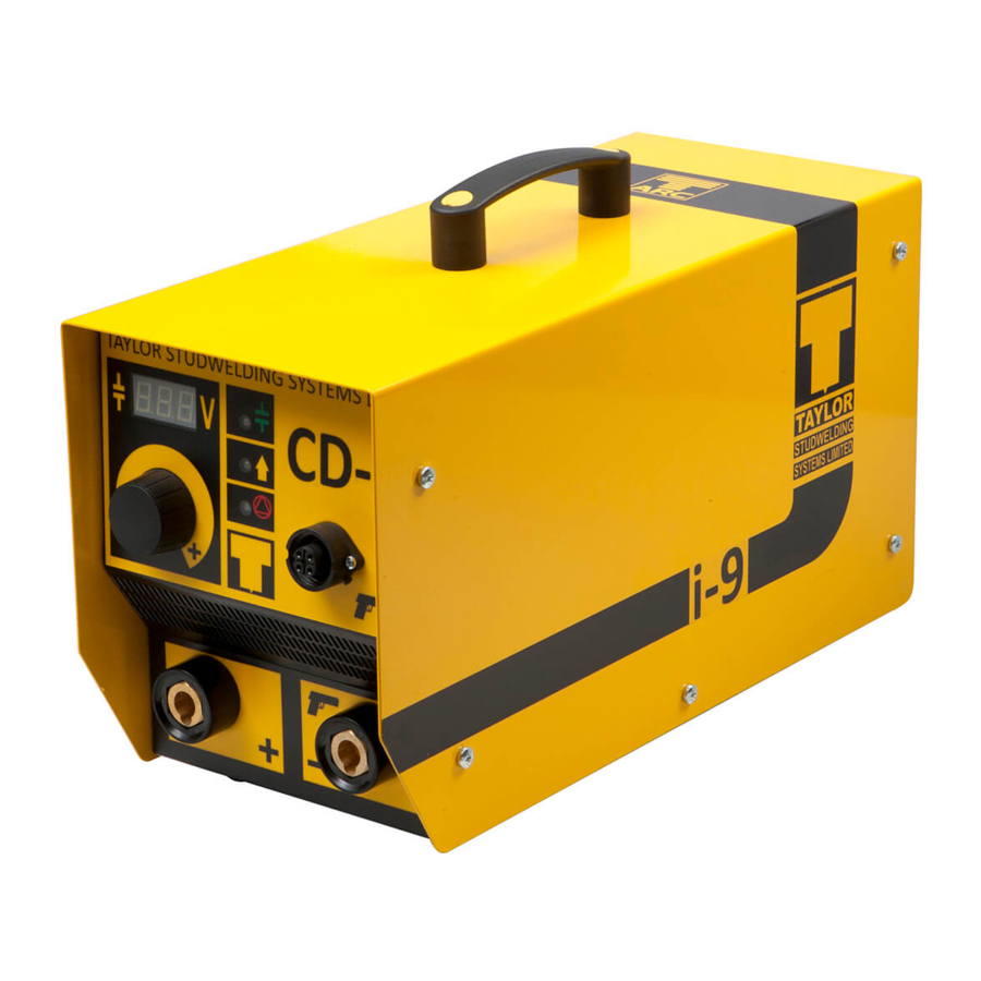
Page 8: Front Panel
GUIDE TO EXTERNAL FEATURES 1 6 2 7 3 8 4 9 ... - Page 9 GUIDE TO EXTERNAL FEATURES 1 2 3 4 5 BACK PANEL 1. RATING/SERIAL PLATE 4. MAIN FUSE 2. ON/OFF SWITCH 5. MAINS INLET ‐ IEC SOCKET OR 3. VENTILLATION FAN/GRILLE ‐ ! DO NOT OBSTRUCT ! FIXED CABLE (SEE INSET) ...
-
Page 10: Setting Up And Welding
SETTING UP AND WELDING Set up the control unit at the place of work, ensuring that the mains switch is in the OFF posi on. Ensure that this is done in line with the notes and safety recommenda ons on pages 5 and 6 of this manual. Plug the controller into the correct mains AC supply. The controller is rated for any single phase AC voltage between 100 and 250VAC at 50Hz. Ensure the correct plug is fi ed for your supply in line with local/ na onal codes. Connect the welding earth cable to the controller panel mounted plug. Note that the cable end plug has a peg which mates with a key slot in the panel mounted socket. IMPORTANT ! Secure the connector with a clockwise turn un l it locks. Failure to do this will result in damage to the connector during welding. A ach the welding earth clamps to the work piece at approximately 180° to each other. This will help to prevent "Arc blow" when welding takes place. Prior to fi ng the clamps, ensure that the contact area of the work piece is free from rust, paint, grease etc. As this will result in a poor welding connec on and poor results. Where possible, route the earth cables away from the operator to prevent the operator being posi oned between ... - Page 11 SETTING UP AND WELDING Connect the welding pistol control cable to the panel mounted socket on the controller. Note that the cable end plug and panel moun ng socket are keyed to prevent incorrect fi ng. Push the plug firmly home and twist the locking ring clockwise to secure the plug in posi on. Prepare the pistol for use in accordance with the guidance given in the document “OPERATING GUIDE FOR CD STUDWELDING PISTOLS TYPE C2 & LG2” which accompanies the type C2 pistol supplied with your controller. The guide contains informa on on : Pistol Setup Spare Parts Accessories Safety V‐4J ...
-
Page 12: Weld Settings
WELD SETTINGS This page and the following are intended as a guide to se ng your machine. The se ngs outlined in the table are only intended as a star ng point. It is possible that the se ngs will give sa sfactory results without adjustment, but in reality the quality of the welding results is governed by many variable factors. These include, most obviously, the welding power and pistol spring pressure as covered in the table, but can also include factors such as stud and work‐piece material type and condi on, ambient temperature, rela ve humidity, quality of supply etc. All of these factors can act on the weld to change the outcome. It is recommended that in all instances, you need to carry out sample welds in your actual condi ons and environment. This will enable you to alter the se ngs, where necessary, to achieve welds that are most acceptable to you. The se ng charts were established with the performance of repe ve weld tests using studs manufactured to the BS EN ISO 13918 standard, in the following materials : Mild Steel, Grade St37‐3 Stainless Steel, Grade 1.4303 Aluminium Alloy, Grade AlMg3 and sheet materials of the following types : ... - Page 13 WELD SETTINGS i8 i8 i9 i9 i10 i10 STUD Ø STUD M VOLTAGE SPRING VOLTAGE SPRING VOLTAGE SPRING M2.5/M3 MS 75 2½ 45 2½ 35 2½ SS 75 2½ 45 2½ 35 2½ AL 80 2½ 50 2½ 35 2½ ...
-
Page 14: Mechanical Tests
WELD TESTING Visual examina on of weld quality can, even with limited experience, provide a useful quality assessment. In such a check the presence of a small even witness of weld material around the base of the stud flange a er welding should be ensured. Poor welds are indicated by excess metal on one side of the welded flange and / or the presence of an undercut or non‐fused area between the stud flange and the parent sheet or plate. Incorrect se ngs, adverse magne c effects etc. such as those at edge welding posi ons or with unbalanced earths and studs welded to the work piece at an angle, the controller and pistol should be examined with a view to correc ng such defects. MECHANICAL TESTS : 1. BENDING. The most easily applied method of tes ng the quality of welded fasteners considered here, involves the use of a bending bar. This bending bar (available from your supplier, see the accessories sec on of this manual) fi ed with the correct size of nozzle for the stud to be tested is used to bend over the stud in accordance with BS EN ISO 14555:2006 specifica on. 2. TORSION. A torsion test provides useful informa on for threaded fasteners. This involves ghtening a nut on the stud against a spacer, suitably relieved to cater for the flange and weld spa er. For quan ta ve assessments a suitably calibrated torque wrench may be used, but at its simplest, a spanner will suffice. ... - Page 15 PARTS LIST & EXPLODED DIAGRAMS 1 2 3 4 5 ...
- Page 16 PARTS LIST & EXPLODED DIAGRAMS SEE PAGES 22 TO 24 FOR A BREAKDOWN OF THE CAPACITOR BANK SEE PAGE 20 FOR A BREAKDOWN SEE PAGE 21 FOR A BREAKDOWN OF THE BASEPLATE OF THE BACK PANEL ...
- Page 17 PARTS LIST & EXPLODED DIAGRAMS ITEM No. OFF PART No. DESCRIPTION 1 1 81‐104‐030 KNOB 2 1 81‐104‐032 KNOB CAP 3 2 Z200‐03‐010 SCREW 4 1 70‐102‐025 PANEL CONTROL SOCKET 5 1 70‐105‐231 CONTROL PANEL OVERLAY 6 1 70‐105‐227 BASEPLATE 7 4 Z200‐03‐006 SCREW 8 4 Z610‐03‐000 WASHER 9 1 70‐105‐220 DISPLAY PCB ...
- Page 18 PARTS LIST & EXPLODED DIAGRAMS 1 2 3 4 5 6 ...
- Page 19 PARTS LIST & EXPLODED DIAGRAMS 1 2 3 4 5 6 7 ITEM No. OFF PART No. DESCRIPTION 1 1 70‐105‐221 MAIN PCB 2 5 Z600‐03‐000 ...
- Page 20 PARTS LIST & EXPLODED DIAGRAMS 13 12 11 10 ...
- Page 21 PARTS LIST & EXPLODED DIAGRAMS 1 8 2 9 3 ...
- Page 22 CIRCUIT SCHEMATIC ‐ WIRING 22 V‐4J ...
- Page 23 EC DECLARATION Responsible Party Name : Taylor Studwelding Systems Ltd Address : Commercial Road Dewsbury West Yorkshire UK WF13 2BD In accordance with the following direc ves : 93/68/EEC ...
Need help?
Do you have a question about the CD-i and is the answer not in the manual?
Questions and answers