
Related Manuals for Taylor SYSTEM CD200 SERIES


Summary of Contents for Taylor SYSTEM CD200 SERIES
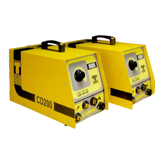
- Page 1 TAYLOR STUDWELDING SYSTEMS LIMITED. OPERATING MANUAL SYSTEM CD200 SERIES COMPACT CAPACITOR DISCHARGE STUDWELDING EQUIPMENT...
-
Page 2: Table Of Contents
INDEX PAGE CONTENT GENERAL INFORMATION INTRODUCTION EQUIPMENT SCHEDULE EXTERIOR FEATURES SAFETY SETTING UP AND WELDING WELD SETTINGS LOCATION METHODS WELD ASSESSMENT / TESTING CONTACT PISTOL EXPLOSION AND PARTS LIST MARK V LIFT GAP PISTOL EXPLOSION AND PARTS LIST CONTROLLER EXPLOSION AND PARTS LIST CIRCUIT SCHEMATIC AVAILABLE ACCESSORIES EC DECLARATION OF CONFORMITY... -
Page 3: General Information
GENERAL INFORMATION MANUFACTURERS DETAILS TAYLOR STUDWELDING SYSTEMS LIMITED COMMERCIAL ROAD DEWSBURY WEST YORKSHIRE WF13 2BD ENGLAND TELEPHONE +44 (0)1924 452123 FACSIMILE +44 (0)1924 430059 e-mail info@taylor-studwelding.com TECHNICAL TEL +44 (0)1924 487703 SALES TEL +44 (0)1924 487701 PURPOSE AND CONTENT OF THIS MANUAL This manual has been written for : The operator of the welding machine. - Page 4 GENERAL INFORMATION FURTHER INFORMATION Should you require additional technical information, please contact us directly (details on page 1) or our local agent / distributor (details of agents etc. can be obtained from us). This manual contains important information which is a pre-requisite for safe operation of the equipment.
-
Page 5: Introduction
INTRODUCTION INTRODUCTION The complete range of Taylor Studwelding Systems Capacitor Discharge units are compact, portable Stud Welding equipment's. The units are specifi- cally designed to enable a small diameter range of ferrous and non-ferrous weld studs to be welded to light gauge, self-finish or pre-coated materials, in most cases with little or no reverse marking. -
Page 6: Equipment Schedule
EQUIPMENT SCHEDULE EQUIPMENT No. OFF DESCRIPTION PART No. SYSTEM CD200 - 66 CONTACT 99-100-110 COMPLETE SYSTEM CD200 - 66 LIFT GAP 99-100-114 COMPLETE SYSTEM CD200 - 99 CONTACT 99-100-111 COMPLETE SYSTEM 200CD - 99 LIFT GAP 99-100-115 COMPLETE SYSTEM CD200 - 132 CONTACT 99-100-119 COMPLETE CD CONTACT PISTOL... - Page 7 EXTERNAL FEATURES FRONT PANEL WELDING VOLTAGE SELECTOR KNOB WELDING VOLTAGE DIGITAL DISPLAY WELDING EARTH PANEL CONNECTIONS WELDING PISTOL PANEL CONNECTION WELDING PISTOL CONTROL SOCKET INDICATOR LED's READY (GREEN) Indicates that the capacitor bank is charged to the pre-selected value and is ready to weld. CHARGING (YELLOW) Indicates that the unit is in the process of charging the...
- Page 8 EXTERNAL FEATURES REAR PANEL SERIAL / RATING PLATE CASING VENTILATION HOLES VENTRAL HOLES NOT SHOWN) BLANKING PLATE or 7 PIN OUTPUT SOCKET. (USED IN AUTOMATIC UNITS ONLY). SWITCHED, FILTERED AND FUSED IEC MAINS INPUT SOCKET. IMPORTANT NOTES ! Due to the power requirements and Electromagnetic emissions produced during normal use, this machine must only be operated in an industrial environment.
-
Page 9: Safety
SAFETY PROTECT YOURSELF AND OTHERS ! Read and understand these safety notices. 1. ELECTRICAL No portion of the outer cover of the welding controller should be re- moved by anyone other than suitably qualified personnel and never whilst mains power is connected. ALWAYS disconnect the mains plug from the socket. - Page 10 SAFETY 3. PERSONNEL SAFETY Arc rays can burn your eyes and skin and noise can damage your hear- ing. Operators and personnel working in close proximity must wear suitable eye, ear and body protection. Fumes and gases can seriously harm your health. Use the equipment only in a suitably ventilated area.
- Page 11 SAFETY 6. INSTALLATION Ensure that the site chosen for the equipment is able to support the weight of the equipment and that it will not fall or cause a danger in the course of its normal operation. Do not hang connecting cables over sharp edges and do not install connecting cables near heat sources or via traffic routes where people may trip over them or they may be damaged by the pas- sage of vehicles (forklifts etc.).
-
Page 12: Setting Up And Welding
SETTING UP & WELDING SETTING UP & WELDING Set up the control unit at the place of work, ensuring that the mains switch is in the OFF position. Ensure that this is done in line with the notes and safety rec- ommendations on pages 7 through 9 of this manual. - Page 13 SETTING UP & WELDING SETTING UP & WELDING Connect the welding pistol cable to the controller. Note that the cable end plug has a peg which mates with a key slot in the panel mounted socket. IMPORTANT ! Secure the connector with a clockwise turn until it locks.
- Page 14 SETTING UP & WELDING SETTING UP & WELDING After setting the chuck, insert it into the pistol chuck holder and push firmly home until it comes to a rest. NOTE! When welding M10 studs or studs between 35 and 50 mm in length, the pistol will require longer tripod legs fitting (see page 34).
- Page 15 SETTING UP & WELDING SETTING UP & WELDING SETTING THE PISTOL MkV LIFT GAP PISTOL (CONTINUED) It is at this point that further twisting of the end cap begins to lift the tripod legs/nosecone away from the plate. The pistol is now in the zero lift position and twisting the rear end cap anti-clockwise by one "click"...
- Page 16 SETTING UP & WELDING SETTING UP & WELDING Place the pistol perpendicular to the work piece with the stud touching down at the desired location to be welded. Press down on the pistol until the legs come firmly into contact with the work piece.
- Page 17 SETTING UP & WELDING SETTING UP & WELDING A cold stud weld is noticeable by undercutting of the flange and lack of / minimal formation of spatter. A cold weld is usually caused by too little energy and / or too high spring pressure. A hot stud weld is noticeable by excessive spatter formation and partial melting of the flange.
-
Page 18: Weld Settings
WELD SETTINGS The following pages (17 to 22) detail the suggested settings for the following CD200 models : 66, 99 & 132 both Contact & Lift Gap The setting charts were established with the performance of repetitive weld tests using the standard equipment's specified above, studs manufac- tured to the BS EN ISO 13918 standard, in the following materials : Mild Steel, Grade St37-3 Stainless Steel, Grade 1.4303... - Page 19 WELD SETTINGS CD200-66 CD200-66 CONTACT CD200-66 GAP STUD STUD SHEET VOLTAGE SPRING VOLTAGE LIFT DIAMETER MATERIAL MATERIAL SETTING SETTING SETTING SETTING M2.5 St37-3 2½ 2½ S304 2½ 2½ ZINTEC 2½ St37-3 2½ 2½ S304 2½ 2½ ZINTEC 2½ 1.4303 2½ 2½...
- Page 20 WELD SETTINGS CD200-66 CD200-66 CONTACT CD200-66 GAP STUD STUD SHEET VOLTAGE SPRING VOLTAGE LIFT DIAMETER MATERIAL MATERIAL SETTING SETTING SETTING SETTING St37-3 2½ 2½ S304 2½ 2½ ZINTEC 2½ 1.4303 2½ 2½ S304 2½ 2½ ZINTEC 2½ AlMg3 St37-3 2½ S304 2½...
- Page 21 WELD SETTINGS CD200-99 CD200-99 CONTACT CD200-99 GAP STUD STUD SHEET VOLTAGE SPRING VOLTAGE LIFT DIAMETER MATERIAL MATERIAL SETTING SETTING SETTING SETTING M2.5 St37-3 2½ 2½ S304 2½ 2½ ZINTEC 2½ St37-3 2½ 2½ S304 2½ 2½ ZINTEC 2½ 1.4303 2½ 2½...
- Page 22 WELD SETTINGS CD200-99 CD200-99 CONTACT CD200-99 GAP STUD STUD SHEET VOLTAGE SPRING VOLTAGE LIFT DIAMETER MATERIAL MATERIAL SETTING SETTING SETTING SETTING St37-3 2½ 2½ S304 2½ 2½ ZINTEC 2½ 1.4303 2½ 2½ S304 2½ 2½ ZINTEC 2½ AlMg3 St37-3 2½ 2½...
- Page 23 WELD SETTINGS CD200-132 CD200-132 CONTACT CD200-132 GAP STUD STUD SHEET VOLTAGE SPRING VOLTAGE LIFT DIAMETER MATERIAL MATERIAL SETTING SETTING SETTING SETTING M2.5 St37-3 2½ 2½ S304 2½ 2½ ZINTEC 2½ St37-3 2½ 2½ S304 2½ 2½ ZINTEC 2½ 1.4303 2½ 2½...
- Page 24 WELD SETTINGS CD200-132 CD200-132 CONTACT CD200-132 GAP STUD STUD SHEET VOLTAGE SPRING VOLTAGE LIFT DIAMETER MATERIAL MATERIAL SETTING SETTING SETTING SETTING St37-3 2½ 2½ S304 2½ 2½ ZINTEC 2½ 1.4303 2½ 2½ S304 2½ 2½ ZINTEC 2½ AlMg3 St37-3 2½ 2½...
- Page 25 METHODS OF STUD LOCATION Economic stud location may be obtained using any one of the following methods, depending on the type of work involved :- Tripod leg assembly. Nose cone assembly. Extended leg assembly. TRIPOD LEG ASSEMBLY. This is generally used for low volume production and one off compo- nents.
-
Page 26: Weld Assessment / Testing
WELD ASSESSMENT / TESTING Visual examination of weld quality can, even with limited experience, provide a useful quality assessment. In such a check the presence of a small even witness of weld material around the base of the stud flange after weld- ing should be ensured. - Page 27 COMPONENT EXPLOSION STANDARD CONTACT PISTOL. 11 12 15 16 17 13 14 18 19 20 21 22 23 24 25 26 27 28 29...
- Page 28 PARTS LIST STANDARD CONTACT PISTOL. ITEM PART No. DESCRIPTION 71-101-018 REAR END CAP 71-101-017 SPRING PRELOAD ADJUSTOR 71-101-016 ADJUSTABLE SPRING SEAT 71-101-014 SPRING 71-101-012 FIXED SPRING SEAT 71-101-011 SHAFT CIRCLIP 71-101-005 PISTOL BODY MOULDING (2 PARTS) 71-101-007 DOWEL PIN 71-101-006 BEARING BUSH 71-101-008 WELDSHAFT 71-101-029 FLEXIBLE BRAID ASSEMBLY 71-101-038 CABLE SPLICING BLOCK...
- Page 29 COMPONENT EXPLOSION MARK V LIFT GAP PISTOL. 15 16 17 19 20 21 22 12 11 10 23 24 25 31 32 33 34 35 36 37 38 39 49 50 51 44 45 46 47...
- Page 30 PARTS LIST MARK V LIFT GAP PISTOL. ITEM PART No. DESCRIPTION Z115-04-010 END CAP SCREW 71-102-067 REAR END CAP 71-102-066 REAR BUSH 71-102-073 DETENT SPRING 81-101-082 DETENT BALL 71-102-075 INDICATOR PIN 71-102-056 SOLENOID COIL COMPLETE 71-102-061 WELDSHAFT 71-102-015 SPIROL PIN 71-102-062 SHAFT BUSH 71-102-069...
- Page 31 PARTS LIST MARK V LIFT GAP PISTOL. ITEM PART No. DESCRIPTION 71-101-009 CONTACT SPRING 71-102-071 SHAFT BEARING Z210-02-010 SCREW (SWITCH / CABLE GRIP) Z600-02-000 WASHER (SWITCH / CABLE GRIP) 71-101-036 TRIGGER BEZEL 71-101-035 TRIGGER PUSH BUTTON 71-101-028 TRIGGER MICRO SWITCH 71-101-027 CABLE GRIP 71-102-029...
- Page 32 COMPONENT EXPLOSION CD200 SERIES CONTROLLER 15, 14, 13 12 11 10...
- Page 33 COMPONENT EXPLOSION CD200 SERIES CONTROLLER ITEM QTY PART No. DESCRIPTION 70-105-014 CARRYING HANDLE 70-105-001 HOUSING COVER 70-105-009 POSITIVE BUSBAR 70-105-008 NEGATIVE BUSBAR 70-102-131 FLYBACK DIODE (66 CONTACT ONLY) 70-102-131 FLYBACK DIODE (ALL OTHER MODELS) 70-105-021 POWER SUPPLY MODULE (CONTACT MODELS ONLY) 70-105-019 POSITIVE CONNECTION CABLE 70-105-018 MOUNTING PILLAR 70-102-046 WELDING THYRISTOR...
- Page 34 COMPONENT EXPLOSION CD200 SERIES CONTROLLER ITEM QTY PART No. DESCRIPTION 70-105-015 CONTROL PANEL OVERLAY 70-105-007 PANEL PLUG LINK BAR 70-102-002 CASING FOOT 70-105-016 CORDSET (UK 230V - IEC) 70-105-017 CORDSET (SCHUKO 230V - IEC) 70-105-028 CORDSET (UK 110V - IEC) 70-105-002 HOUSING BASEPLATE 70-105-013 BALLAST RESISTOR 70-105-020 NEGATIVE CONNECTION CABLE...
-
Page 35: Circuit Schematic
CIRCUIT SCHEMATIC CD200 SERIES CONTROLLER POWER DISPLAY SUPPLY 16 WAY RIBBON CABLE UNIT 10 WAY RIBBON CABLE DANGER! HIGH VOLTAGE 6 WAY HEADER ENCLOSURE GREEN WHITE CONTAINS ORANGE NO USER PURPLE SERVICE- ABLE BLACK BLACK PARTS FLYBACK DIODE(S) CAPACITOR BANK BROKEN LINE INDICATES LIFT GAP... - Page 36 ACCESSORIES STANDARD TRIPOD LEG ASSEMBLY. COMPLETE ASSEMBLY AVAILABLE UNDER PART NUMBER : 79-101-050 (STANDARD) NOTE # LONG LEGS ARE USED WHEN WELDING STUD LENGTHS BETWEEN 35 AND 50, OR WHEN WELDING M10 STUDS. ITEM QTY DESCRIPTION PART No. TRIPOD LEG (STANDARD) 79-101-052 TRIPOD LEG (LONG.
- Page 37 ACCESSORIES STANDARD NOSE CONE ASSEMBLY. COMPLETE ASSEMBLY AVAILABLE UNDER PART NUMBERS : Ø30 mm ASSY 79-101-070 Ø25.4 mm (1”) ASSY : 79-101-069 Ø22 mm ASSY 79-101-068 ITEM QTY DESCRIPTION PART No. Ø30 mm NOSE CONE 79-101-072 Ø22 mm NOSE CONE 79-101-078 Ø25.4 mm NOSE CONE 79-101-077...
- Page 38 ACCESSORIES STANDARD SCREW-IN NOSE CONE ASSEMBLY. COMPLETE ASSEMBLY AVAILABLE UNDER PART NUMBERS : Ø30 mm ASSY 79-101-082 Ø25.4 mm (1”) ASSY : 79-101-081 Ø22 mm ASSY 79-101-080 NOTE : FIT CHUCKS WITH 12 mm LONG BACKSTOP 79-101-071 & 2 LOCKING NUTS ITEM QTY DESCRIPTION PART No.
- Page 39 ACCESSORIES EXTENDED LEG ASSEMBLY. COMPLETE ASSEMBLY AVAILABLE UNDER THE FOLLOWING PART NUMBERS : C/W TRIPOD LEGS 79-101-148 C/W ø30 NOSE CONE 79-101-147 ITEM QTY DESCRIPTION PART No. EXTENDED LEG 81-101-004 GRUB SCREW Z430-05-006 PIVOTAL GRIP INSERT 79-101-142 GRUB SCREW Z400-05-004 FRONT END CAP 79-101-141 CENTRING GUIDE (3 mm +)
- Page 40 ACCESSORIES OFFSET CHUCK ADAPTOR COMPLETE ASSEMBLY AVAILABLE UNDER PART NUMBER : 79-101-110 NOSE CONE CENTRING DEVICE COMPLETE ASSEMBLIES AVAILABLE UNDER PART NUMBERS : Ø22 CUP & ROD 79-101-112 Ø25.4 (1”) CUP & ROD 79-101-113 Ø30 CUP & ROD 79-101-114 ITEM QTY DESCRIPTION PART No.
- Page 41 ACCESSORIES OFFSET CHUCK ADAPTOR COMPLETE ASSEMBLY AVAILABLE UNDER PART NUMBER : 79-101-120 ITEM DESCRIPTION PART No. BENDING BAR 79-101-121 M10 NOZZLE 79-101-128 M8 NOZZLE 79-101-127 M6 NOZZLE 79-101-126 M5 NOZZLE 79-101-125 M4 NOZZLE 79-101-124 M3 NOZZLE 79-101-123...
- Page 42 ACCESSORIES CHUCKS / COLLETS EARTH TAG CHUCK PART No. 79-101-019 LARGE BRACKET CHUCK (NOT ILLUSTRATED) PART No. 79-101-022 STANDARD CD CHUCK WITH BACKSTOP PART No. s M2.5 79-101-002 79-101-003 79-101-004 79-101-005 79-101-006 M7.1 79-101-007 79-101-008 STANDARD M10 CHUCK WITH BACKSTOP PART No.
-
Page 43: Ec Declaration Of Conformity
This statement is invalid if any modifications are carried out on the machinery without the prior written approval of Taylor Studwelding Systems Ltd. ————————————————————————————————————- DESCRIPTION OF MACHINE : Capacitor Discharge Studwelding Equipment... -
Page 44: Emc Certificate
EMC CERTIFICATE...
Need help?
Do you have a question about the SYSTEM CD200 SERIES and is the answer not in the manual?
Questions and answers