RSP TC5 Product Manual
Tool changer
Hide thumbs
Also See for TC5:
- Installation and maintenance manual (20 pages) ,
- Installation and maintenance manual (22 pages)

Related Manuals for RSP TC5


Summary of Contents for RSP TC5
- Page 1 Product Manual m0403 Tool changer TC5 M0109-1 Tool changers | Swivels | Swivel tool changers | Grippers | Hose packages | Valve units | Tool systems...
- Page 2 M0109-1 ver 2.2...
- Page 3 The information in this document is subject to change without prior notice and should not be regarded as an undertaking from Robot System Products AB. Robot System Products AB assumes no responsibility for errors that may occur in this document. Robot System Products AB bears no responsibility for damage that is incurred by the use of this document, or the software or hardware described in this document.
-
Page 4: Table Of Contents
2.1.2 Tool changer with air, TC5-6. Article no: P1001 .............. 11 2.1.3 Tool attachment TA5-6, Article no: P1002 ............... 12 2.1.4 Tool changer with air and electric signals, TC5-4E. Article no: P1003 ......13 2.1.5 Tool attachment TA5-6, Article no: P1004 ............... 14 2.1.6 Pneumatic diagram for TC5 and TA5 ................ - Page 5 4.3.2 Cleaning of tool attachment....................29 4.4 Replacement of wear parts ..................30 4.4.1 Replacement of air sealings ..................... 30 4.4.2 Replacement of signal pins (TC5-4E only) ............... 30 4.5 Complete service of tool changer ................31 4.6 Replacement of tool changer ..................31 5 SPARE PARTS .....................
-
Page 6: Introduction
TrueConnect™ tool changing mechanism with our swivel technology, combining the best out of two technologies. Robot System Products’ product lines are available for all major robot brands and come with complete documentation. 3D-models for simulation are available for download at: www.rsp.eu.com M0109-1 ver 2.2... -
Page 7: Safety
1.1 Safety 1.1.1 General The integrator installing the tool changer into the system must follow the safety demands stated in standards and provisions applicable in the country where the tool changer system is to be installed. The products are all prepared for CE-certification. The user of the Robot System Products tool changer is responsible that law and directives applicable in respective countries, with regards to safety, are followed. -
Page 8: Description Of Rsp Tool Changers
1.2 Description of RSP tool changers Our tool changers enable robots to handle and switch between multiple tools. They are built to ensure reliable and smooth operation, being compact with low weight and robust design and incorporating many safety features. Depending on model and options, electrical signals, weld and servo power, data, water and compressed air are transferred from the robot side to the tool. -
Page 9: Technical Specifications
The tool changer TC5-6 transfers compressed air to the tool. It can be equipped with transfer of electrical signals, via spring loaded signal pins, to the tool attachment. The electrical version is designated ’E’. -
Page 10: Coordinate System Definition
2.1.1 Coordinate System Definition A tool changer adds load to the robot. If the arm and tool loads are not stated correctly during programming the behaviour of the robot and the wear of the equipment will be affected. Information about weight and centre of gravity can, in accordance with the co-ordinate system stated below, be found in the technical specification tables of the tool changer. -
Page 11: Tool Changer With Air, Tc5-6. Article No: P1001
2.1.2 Tool changer with air, TC5-6. Article no: P1001 Tool changer TC5-6 transfers 6 pneumatic channels to the tool attachment. To be used together with tool attachment P1003. Technical data Working temperature +10°C−+60°C Bolt pattern ISO 9409-1 31.5-4-M5 Maximum tool load Fz (static) ±50 N... -
Page 12: Tool Attachment Ta5-6, Article No: P1002
2.1.3 Tool attachment TA5-6, Article no: P1002 Tool attachment TA5-6 transfers 6 pneumatic channels to the tool. To be used together with tool changer P1001. Technical data Working temperature +10°C−+60°C Bolt pattern ISO 9409-1 31.5-4-M5 Weight 0.06 kg Maximum tool load Fz (static) ±50 N M6-screws) -
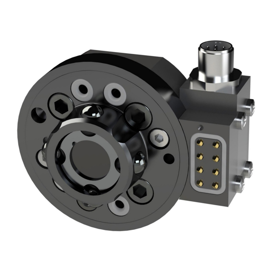
Page 13: Tool Changer With Air And Electric Signals, Tc5-4E. Article No: P1003
2.1.4 Tool changer with air and electric signals, TC5-4E. Article no: P1003 Tool changer TC5-6 transfers 6 pneumatic channels to the tool attachment. To be used together with tool attachment P1004. Technical data Working temperature +10°C−+60°C Bolt pattern ISO 9409-1 31.5-4-M5... -
Page 14: Tool Attachment Ta5-6, Article No: P1004
2.1.5 Tool attachment TA5-4E, Article no: P1004 Tool attachment TA20-4 transfers 6 pneumatic channels to the tool. To be used together with tool changer P1003. Technical data +10°C−+60°C Working temperature Bolt pattern ISO 9409-1 31.5-4-M5 Weight 0.08 kg Maximum tool load Fz (static) ±50 N M6-screws) -
Page 15: Pneumatic Diagram For Tc5 And Ta5
2.1.6 Pneumatic diagram for TC5 and TA5 NOTE! Ducts 1 and 2 are not available for TC5-4E and TA5-4E! M0109-1 ver 2.2... -
Page 16: Circuit Diagram E0211-006 For P1003
2.1.7 Circuit diagram E0211-006 for P1003 M0109-1 ver 2.2... -
Page 17: Circuit Diagram E0211-007 For P1004
2.1.8 Circuit diagram E0211-007 for P1004 M0109-1 ver 2.2... -
Page 18: Options To Tool Changers And Tool Attachment
2.2 Options to tool changers and tool attachment 2.2.1 Signal interface, 8 signals, robot side. Article no: P1013 Transfers 8 electrical signal to the tool attachment. Can be mounted at two different positions on the tool changer. To be used with option P1014 on the tool attachment. Technical data Weight 0.04 kg... -
Page 19: Signal Interface, 8 Signals, Tool Side. Article No: P1014
2.2.2 Signal interface, 8 signals, tool side. Article no: P1014 Transfers 8 electrical signal to the tool. Can be mounted at two different positions on the tool attachment. To be used with option P1013 on the tool changer. Technical data Weight 0.02 kg Electrical signals... -
Page 20: Tool Stand Kit. Article No: P1005
5 kg 2.2.4 Robot adaptation kit The flange of TC5 has fastening holes in accordance with ISO 9409-1-40-4-M6. Adaptation plates, which are mounted between the tool changer and the robot flange, are available for other bolt circles. The order number is customer specific, depending on the robot. -
Page 21: Limitation Of Robot Movement
2.2.5 Limitation of Robot movement There can be some limitations on the movement of axis 5 for some robot models. Contact Robot System Products for more information. 2.2.6 Connection kits and cables Part Description number Electrical connection kit for P0103, M12-8P – M12 8S, 2 meter cable (0,25 mm²). P0025 Electrical connection kit for P0103, M12-8P –... -
Page 22: Installation Of Tool Changer On Robot
Connect air hoses Connect the air hoses according to markings. NOTE! Pneumatic diagram is found in section 2.1.8. Connect electrical signals (TC5-4E Connect signal contact M12 8p. only) Power on Unlock the circuit breaker and switch the power on. -
Page 23: Installation Of Tool Attachment To Gripper/Tool
3.4 Installation of tool attachment to gripper/tool Action Note Safety Read the safety section (1.1). Mount guide pin Press the guide pin into the corresponding holes on the tool. Fit tool attachment Lift and fit the tool attachment, using the guide pin, into its guide hole. Mount tool attachment Mount the tool attachment using a torque wrench with either M4 or M5... -
Page 24: Hints
3.5 Hints 3.5.1 Programming The following will ensure a correct docking position. Action Attach a spare tool attachment to the tool changer. Position the spare tool attachment above the tool attachment that is mounted on the tool. The correct position is found when the tool attachments are parallel, centered and the engraved arrows are on the same line. -
Page 25: Maintenance And Service
4 MAINTENANCE AND SERVICE 4.1 Maintenance chart The tool changer and tool attachment must be maintained regularly to ensure proper function. The specified intervals are approximate and valid under normal conditions. Under extreme conditions, such as dirty environments or extreme robot movements, the intervals should be shortened. -
Page 26: Recommended Tools For Maintenance
4.1.2 Recommended tools for maintenance Tools Applications Complete set of Allen keys For dismounting and mounting. Pair of pliers For dismounting the signal pins. Screw driver For removing the air sealings. Torque wrench For all socket head cap screws 4.1.3 Wear parts Wear parts should be replaced before considerable damage occurs. -
Page 27: Activities And Intervals On Tool Attachment
4.2.1 Inspection of the tool changer Visually check the following: Check Note Air sealings Not worn, damaged or dirty Locking balls Greased. Not dirty Signal pins (TC5-4E only) Not damaged or dirty Cables Not squeezed or damaged All parts No wear All parts No damage... -
Page 28: Cleaning
NOTE! It is important that this is done or there might else be a risk that the tool attachment jams. Clean signal pins (TC5-4E only) Clean only the contact surfaces! NOTE! Avoid cleaning solvent in the housing. General cleaning Clean the swivel with tool changer in general. -
Page 29: Cleaning Of Tool Attachment
4.3.2 Cleaning of tool attachment Action Note Clean grooves Wipe the grooves for the locking balls with a cloth. Clean contact surfaces (TA5-4E only) Clean the signal contact surface with a cloth. General cleaning Clean the tool attachment in general. M0109-1 ver 2.2... -
Page 30: Replacement Of Wear Parts
Glue the new air sealing in the sealing groove. Use a small amount of Loctite 480 (or similar). Press the sealing 60-120 seconds until the glue hardens. 4.4.2 Replacement of signal pins (TC5-4E only) Replace a signal pin when worn or damaged. Action Note... -
Page 31: Complete Service Of Tool Changer
We recommend a complete service on tool changers to be carried out every 5 years. This will ensure proper function and increase the lifespan of the tool changer considerably. We further recommend that the maintenance shall be carried out by qualified RSP personnel. Please contact us for a quotation. - Page 32 WARNING! The tool changer may cause personal injury and equipment damage if dropped. NOTE! Be careful not to damage the signal pins (TC5-4E only). Dismount tool changer NOTE! A guide pin is mounted between the tool changer and the robot flange...
-
Page 33: Spare Parts
5 SPARE PARTS 5.1 Part list for tool changer P1001 and P1003 Item Description Part number Wear part TC5-6 P1001 Air sealing I0812 Signal interface P1113 Spring loaded signal pins I0154 Screw MRX 3x25 5.2 Part list for tool attachment P1002 and P1004... -
Page 34: Part List For Signal Interface P1013
5.3 Part list for signal interface P1013 Item Description Part number Wear part Screw MRX 3x25 Signal contact P0162 Signal pins I0154 O-ring P0185-007A 5.4 Part list for signal interface P1014 Item Description Part number Wear part Screw MRX 3x20 Cable P0208-032 M0109-1 ver 2.2... -
Page 35: Disposal And Recycling
6 DISPOSAL AND RECYCLING Taking care of spent equipment Used equipment must be taken care of in an environmentally-friendly way. When disposed of, a major share of the material, or its energy content, can be recycled. The quantities possible to recycle vary depending on technical resources and practises in respective country. - Page 36 M0109-1 ver 2.2...
- Page 37 M0109-1 ver 2.2...
- Page 38 M0109-1 ver 2.2...
Need help?
Do you have a question about the TC5 and is the answer not in the manual?
Questions and answers