
Related Manuals for RSP TC60


Summary of Contents for RSP TC60
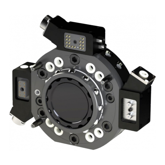
- Page 1 Installation and Maintenance Manual Tool changers TC60, TC120, TC180 M0627-1 Tool changers | Swivels | Swivels with Tool changers | Grippers | Hose packages | Valve Units | Tool systems...
- Page 2 M0627-1 version 3.3...
- Page 3 The information in this document is subject to change without prior notice and should not be regarded as an undertaking from Robot System Products AB. Robot System Products AB assumes no responsibility for errors that may occur in this document. Robot System Products AB bears no responsibility for damage that is incurred by the use of this document, or the software or hardware described in this document.
-
Page 4: Table Of Contents
4.3 Replacement of wear parts ..................26 4.3.1 Replacement of air sealings on TC180 ................26 4.3.2 Replacement of air sealings on TC60, TC120 and air module, TC-side......27 4.3.3 Replacement of guide pins (P1314) on tool changers ............. 28 4.3.4 Replacement of spring-loaded signal pins on signal interface, TC-side ...... -
Page 5: Introduction
1.1 Installation and Maintenance manual This document describes how the tools changers, TC60, TC120 and TC180, including corresponding tool attachments and options for transfer of power, signals, water and air are installed and replaced. In addition, the document describes required maintenance activities, including inspection, cleaning, lubrication, replacement of wear parts, required tools and products and disposal and recycling. -
Page 6: Safety
1.2 Safety 1.2.1 General The integrator installing the tool changer into the system must follow the safety demands stated in standards and provisions applicable in the country where the tool changer system is to be installed. The products are all prepared for CE-certification. The user of the Robot System Products tool changer is responsible that law and directives applicable in respective countries, with regards to safety, are followed. -
Page 7: Tightening Torques
Glue Loctite 6300 (or similar) For gluing the guide pins. Glue Loctite 480 (or similar) For gluing air sealings (TC60, TC120 and option two air, P1325). Cloth Lint free cloth For cleaning. NOTE! Chemical resistance protective gloves are recommended when using grease or cleaning agents such as industrial alcohol. -
Page 8: Installation
2 INSTALLATION 2.1 Installation of tool changer on robot Action Note Safety Read the safety section (1.2). Service position Place the robot in service position Power off Switch the power off and lock the circuit breaker NOTE! Read the safety chapter for the robot. - Page 9 Connect air hoses Connect air hoses to the hose fittings. Pneumatic diagrams are found in the Product Description of respective unit. Connect signals Connect electrical connectors in accordance with selected options. Circuit diagrams are found in the Product Description of respective unit. Power on Unlock circuit breaker and switch power on.
-
Page 10: Installation Of Tool Attachment To Tool
2.2 Installation of tool attachment to tool Action Note Safety Read the safety section (1.2). Mount guide pin Press, when required, a guide pin (CPK 8x) into its position on the tool. Fit tool attachment Lift the tool attachment to the tool and fit using the guide pin, if applicable, into its appropriate guide hole. -
Page 11: Mounting Of Parking Bracket Plate
Connect air hoses Connect air hoses to the hose fittings on the tool attachment or selected option. Pneumatic diagrams are found in the Product Description of respective unit. Connect signals Connect electrical connectors in accordance with selected options. Circuit diagrams are found in the Product Description of respective unit. -
Page 12: Mounting Of Parking Bracket Kit
2.4 Mounting of parking bracket kit Safety Read the safety section (1.2). Mount screws Mount the four enclosed M8x12- screws on the two brackets. See tightening torques above. Fit and mount parking bracket plate Fit the parking brackets (P1313) to the tool attachment and mount with the two enclosed M6-screws. -
Page 13: Maintenance And Service
3 MAINTENANCE AND SERVICE The tool changer and tool attachment must be maintained regularly to ensure proper function. The specified intervals are approximate and valid under normal conditions, corresponding to 2 tool changes per minute during 2 work shifts per working day, i.e. 42.000 changes per month. Under extreme conditions, such as dirty environments or extreme robot movements, the intervals should be shortened. -
Page 14: Every Six-Months Or 250,000 Tool Changes
3.1.2 Every six-months or 250,000 tool changes The following maintenance activities should be carried out every six-months or after every 250,000 tool changes, whichever comes first. Activity Equipment Description Cleaning Tool changer Locking balls Clean locking balls and add new lubrication, (section 3.2.3). -
Page 15: Specification Of Maintenance Activities
3.2 Specification of maintenance activities 3.2.1 Visual inspection of tool changer The following maintenance activities should be carried out on the TC every 2 week. Action Note Check locking balls Check each ball to make sure it moves freely. For cleaning and lubrication of balls see section 3.2.3. -
Page 16: Visual Inspection And Cleaning Of Tool Attachment (Every 2Nd Week)
Check servo power sockets Check that the areas around the sockets are clean. For cleaning and lubrication see section 3.2.3. Check that the sockets are not worn-out or damaged. For replacing the signal or servo power interface see section 4.3.5. NOTE! When interface options, P1307, P1356, P1354 are used! Check high voltage socket... - Page 17 Check servo power pins Check that the signal and servo power pins are clean. For cleaning and lubrication see section 3.2.4. Check that the pins or interface are not worn-out or damaged. For replacing the signal or servo power interface see section 4.3.6. NOTE! When interface options, P1308, P1357, P1355 are used! Check high voltage pins...
-
Page 18: Th Month Or 250,000 Tool Changes)
3.2.3 Cleaning and lubrication of tool changer The following maintenance activities should be carried out on the TC every 6 month or after 250,000 tool changes, whichever comes first. Action Note Clean locking balls Check the locking balls and wipe them clean with a lint free cloth. - Page 19 Lubricate guide pins Apply a small amount of grease (Molykote BR2Plus) on the guide pins. Clean air sealings Wipe air sealings clean with a lint free cloth. Clean spring-loaded signal pins Clean the contact surfaces of the spring-loaded signal pins with a nylon brush.
- Page 20 Lubricate signal and power sockets Apply a small amount of grease (Electrolube SGB) in each signal and servo power socket. Clean high voltage socket Wipe the area around the high voltage socket clean. Lubricate high voltage socket Apply a small amount of grease (Electrolube SGB) in the high voltage sockets.
-
Page 21: Cleaning And Lubrication Of Ta (Every 6Th Month Or 250,000 Tool Changes)
3.2.4 Cleaning and lubrication of tool attachment The following maintenance activities should be carried out on the TA every 6th month or after 250,000 tool changes, whichever comes first. Action Note Clean locking cavities Clean the cavities of the locking balls. -
Page 22: Dismounting And Replacement
4 DISMOUNTING AND REPLACEMENT 4.1 Replacement of tool changer Action Note Safety Read the safety section (1.2). Dismount tool Leave tool, with tool attachment mounted, in tool stand. Service position Place the robot in service position. NOTE! The tool change function shall be in locked position. - Page 23 Remove screws Remove the screws holding the tool changer to the robot flange. WARNING! The tool changer is heavy and may cause personal injury and equipment damage if dropped. Dismount tool changer NOTE! Be careful not to damage the signal pins at the tool side of the tool changer.
-
Page 24: Replacement Of Tool Attachment
4.2 Replacement of tool attachment Action Note Safety Read the safety section (1.2). Undock tool Place and undock tool attachment, with tool mounted, in a safe and fully supported position for dismounting. Dismount hoses Dismount the water/air hoses from the tool attachment. - Page 25 M6/M8 Dismount tool attachment NOTE! A guide pin is mounted between the tool attachment and the tool. Clean the flange at the tool Mount tool attachment Follow instructions in section 2.2. M0627-1 version 3.3...
-
Page 26: Replacement Of Wear Parts
4.3 Replacement of wear parts 4.3.1 Replacement of air sealings on TC180 Action Note Remove air sealings Remove the air sealings with a screw driver. NOTE! There are totally 8 air sealings on the TC180. Clean sealing holes Wipe clean the sealing holes. Remove all remaining parts of the sealings. -
Page 27: Replacement Of Air Sealings On Tc60, Tc120 And Air Module, Tc-Side
4.3.2 Replacement of air sealings on TC60, TC120 and air module, TC-side Action Note Remove air sealings Remove the air sealings with a screw driver. NOTE! There are totally 8 air sealings on TC60 and TC120 and two air sealings on the air module. -
Page 28: Replacement Of Guide Pins (P1314) On Tool Changers
4.3.3 Replacement of guide pins (P1314) on tool changers Action Note Enter the puller housing of the Mount puller housing Guide pin puller (VA0182-001) over the guide pin. Mount puller screw Enter the puller screw through the puller housing and guide pin. Fasten to the tool changer by screwing clockwise with a 13 mm spanner. -
Page 29: Replacement Of Spring-Loaded Signal Pins On Signal Interface, Tc-Side
4.3.4 Replacement of spring-loaded signal pins on signal interface, TC-side Action Note Switch power off Switch the power off and lock the circuit breaker. Remove signal pins Pull out the signal pins with a pair of pliers. Replace signal pins Fit the new signal pins by pushing them into the sleeves. -
Page 30: Replacement Of Signal, Servo Power, High Voltage Interface And Air Module, Tc-Side
4.3.5 Replacement of signal, servo power, high voltage interface and air module, TC-side Action Note Power off Switch the power off and lock the circuit breaker. Disconnect interface Remove connector from the servo power interface. Release interface Unscrew the four screws and release the signal interface/air module. -
Page 31: Replacement Of Signal Interface/Air Module, Ta-Side
4.3.6 Replacement of signal interface/air module, TA-side Action Note Undock tool attachment Undock tool attachment, switch power off and lock the circuit breaker. Disconnect signals/air Disconnect signals/air from the module. Release interface Unscrew the four screws and release the signal interface/air module. -
Page 32: Replacement Of O-Rings On Signal Interface, Ta-Side
4.3.7 Replacement of O-rings on signal interface, TA-side Replace O-rings when worn-out or damaged. Action Note Remove O-rings Remove the O-ring/O- rings on the tool attachments signal contact. Replace O-rings Put small amount of grease (Magnalube-G) on the new O-rings before they are mounted. -
Page 33: Disposal And Recycling
5 DISPOSAL AND RECYCLING Taking care of spent equipment Used equipment must be taken care of in an environmentally-friendly way. When disposed of, a major share of the material, or its energy content, can be recycled. The quantities possible to recycle vary depending on technical resources and practises in respective country. - Page 34 M0627-1 version 3.3...
- Page 35 M0627-1 version 3.3...
- Page 36 M0627-1 version 3.3...
Need help?
Do you have a question about the TC60 and is the answer not in the manual?
Questions and answers