
Related Manuals for RSP TPS400


Summary of Contents for RSP TPS400
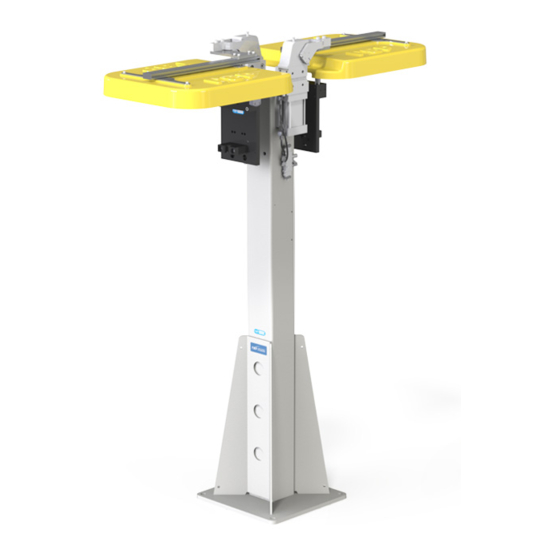
- Page 1 Product Manual Tool parking system TPS400 M8307-1 Tool changers | Swivels | Swivel tool changers | Grippers | Hose packages | Valve units | Tool systems...
- Page 2 M8307-1 version 2.4...
- Page 3 The information in this document is subject to change without prior notice and should not be regarded as an undertaking from Robot System Products AB. Robot System Products AB assumes no responsibility for errors that may occur in this document. Robot System Products AB bears no responsibility for damage that is incurred by the use of this document, or the software or hardware described in this document.
-
Page 4: Table Of Contents
2.1.1 Complementary products ....................8 2.2 Tool parking system single, TPS400-1. Articles: P8365 and P8385 ......9 2.3 Tool parking system double, TPS400-2. Articles: P8366 och P8386 ......10 2.4 Tool parking system single, TPS400-1. Article: P8383 ..........11 2.5 Tool parking system single, TPS400-2. Article: P8384 ..........12 3 TOOL PARKING SYSTEM COMPONENTS ............13... - Page 5 5 INSTALLATION ......................34 5.1 Tightening torques ......................34 5.2 Recommended tools for installation ................34 5.3 Installation of tool hanger on the tool stand column ............ 35 5.4 Mounting of tool in stand sensor with spacer ............... 36 5.5 Mounting of tool present sensor ................... 37 5.6 Mounting of tool plate on tool attachment ..............
-
Page 6: Introduction
With RSPs unique CiRo-technology cables and hoses can be freely selected with high robot flexibility maintained, and the space requirements reduced. RSP’s integrated Tool systems are delivered as complete plug-and-play solutions designed for quick and simple installation. -
Page 7: Safety
1.1 Safety 1.1.1 General The integrator installing the tool parking system must follow the safety demands stated in standards and provisions applicable in the country where the tool parking system is installed. The user of the Robot System Products tool parking system is responsible that law and directives applicable in respective countries, with regards to safety, are adhered to. -
Page 8: Technical Specifications
The tool parking systems are designed both for material handling and spot-welding applications. The RSP tool parking system is a modular unit, easy to install with a reliable design and several options, which also can be ordered as accessories for retrofitting. RSP offers a variety of... -
Page 9: Tool Parking System Single, Tps400-1. Articles: P8365 And P8385
2.2 Tool parking system single, TPS400-1. Articles: P8365 and P8385 Tool parking system single P8365 and P8385 shall be used together with the tool changers TC240, TC480, TC720 and corresponding tool attachments. P8365 should be used together with safety signal modules P7501-xxx. P8385 can be used together with tool in stand sensor assembly, P8364, and tool present sensor, P8312. -
Page 10: Tool Parking System Double, Tps400-2. Articles: P8366 Och P8386
2.3 Tool parking system double, TPS400-2. Articles: P8366 och P8386 Tool parking system double P8366 and P8386 shall be used together with the tool changers TC240, TC480, TC720 and corresponding tool attachments. P8366 should be used together with safety signal modules P7501-xxx. P8386 can be used together with tool in stand sensors assembly, P8364, and tool present sensors, P8312. -
Page 11: Tool Parking System Single, Tps400-1. Article: P8383
2.4 Tool parking system single, TPS400-1. Article: P8383 Tool parking system single P8383 shall be used together with the tool changer TC500 and tool attachment TA500. P8383 can be used together with tool in stand sensor assembly, P8364, and tool present sensor, P8312. -
Page 12: Tool Parking System Single, Tps400-2. Article: P8384
2.5 Tool parking system single, TPS400-2. Article: P8384 Tool parking system single P8384 shall be used together with the tool changers TC500 and tool attachments TA500. P8384 can be used together with tool in stand sensors assembly, P8364, and tool present sensors, P8312. -
Page 13: Tool Parking System Components
3 TOOL PARKING SYSTEM COMPONENTS 3.1 Tool stand columns. Article: P8380 The tool stand column P8380 gives together with the tool hanger P8302 and tool plate P8303A a robust tool parking system for easy tool changing. The tool stand column comes in different heights and is prepared for mounting of a single or double hanger, dust cover, connection modules and valve units. -
Page 14: Dust Covers With Pneumatic Tilting Clamp
3.2 Dust covers with pneumatic tilting clamp The options P8327, P8377 and P8379 (dust covers with pneumatic tilting clamp) shall be mounted on the tool stand column P8380. The dust covers are used for effectively protecting the tool and tool attachment when docked on the tool stand. -
Page 15: Dust Cover With Pneumatic Tilting Clamp, Large. Articles: P8327/P8377
3.2.1 Dust cover with pneumatic tilting clamp, large. Articles: P8327/P8377 Dust cover with pneumatic tilting clamp large P8327 (drawing above) and P8377 should be used together with tool changers TC240, TC480, TC720 with corresponding tool attachments. NOTE The dust cover P8377 has a vertical offset of 50 mm and shall be used when an extended free space under the dust cover is required. -
Page 16: Valve Unit For Dust Cover. Article: P8308A
3.3 Valve unit for dust cover. Article: P8308A A bi-stable 5/2-valve to be mounted on the tool stand column P8380 and used together with P8327, P8377 or P8379 (dust covers with pneumatic tilting clamps). Technical data Weight 0,1 kg Electrical signals Circuit diagram E0186-056 (section 3.3.1) M8 4-pole A-code male... -
Page 17: Circuit Diagram E0186-056
3.3.1 Circuit diagram E0186-056 M8307-1 version 2.4... -
Page 18: Tool Hanger. Article: P8302
3.4 Tool hanger. Article: P8302 The tool hanger P8302, mounted on the tool stand column P8380, gives together with tool plate P8303A a robust tool parking system for easy tool changing. To be mounted using mounting kit for tool hanger, P8370. Technical data Weight 8.3 kg... -
Page 19: Load Diagram For Tool Parking System
3.5 Load diagram for tool parking system The diagram shows the load corresponding to a maximum displacement of 0.5 mm of the tool (including tool attachment) at its point of gravity. NOTE! The displacement of the docking position for drop off/pick up depends on the distance from the tool plate to the tool attachment. -
Page 20: Options
4 OPTIONS 4.1 Tool plate. Article: P8303A The tool plate P8303A, mounted on the tool attachment, gives together with tool hanger P8302 and tool stand column P8380 a robust tool parking system for easy tool changing. NOTE! When used in combination with the safety signal modules P7501-xxx the tool plate P8303A can be used together with tool-in-stand sensor, P8369, to get a presence signal for the safety logic. -
Page 21: Extension For Tool Hanger Kit. Article: P8371 / P8381
4.2 Extension for tool hanger kit. Article: P8371 / P8381 The tool hanger extension P8371 shall be mounted between the tool stand column, P8380, and the tool hanger, P8302 in combination with dust cover with pneumatic tilting clamp large, P8327/P8377. The tool hanger extension P8381 shall be used in combination with dust cover with pneumatic tilting clamp small, P8379. -
Page 22: Spacer Between Tool Attachment And Tool Plate. Article: P0186-049
4.3 Spacer between tool attachment and tool plate. Article: P0186-049 The spacer P0186-049 shall be mounted between the tool attachment and tool plate. Technical data Article number Width Weight P0186-049 50 mm 0.7 kg 4.4 Tool present sensor, inductive. Article: P8312 To be mounted on the tool hanger, a 0.8 meter cable is included. -
Page 23: Tool In Stand Sensor, Passive Side. Article: P8369
4.5 Tool in stand sensor, passive side. Article: P8369 For the tool changers TC240, TC480 and TC720, equipped with safety signal module P7501- xxx, the tool in stand sensor P8369 shall be mounted on tool stand hanger and used together with I1171 mounted on the tool plate. -
Page 24: Spacer For Tool In Stand Sensor. Article: P8373
4.7 Spacer for tool in stand sensor. Article: P8373 Spacers for mounting of passive tool in stand sensor P8369 on the tool hanger and the tool in stand sensor I1171 on the tool plate. Technical data Weight 0.1 kg Thickness 22 mm NOTE! To be used together with TA720 in order to avoid collision between sensor cable and tool attachment. -
Page 25: Connection Module. Article: P8372
4.9 Connection module. Article: P8372 Option for tool parking system single P8365, P8385 and P8383. Technical data Electrical signals Circuit diagram E0186-062-1 (section 4.15) Input Push Pull RJ45 Profinet Push Pull power Power supply 24V M12 4-pin, female (tilting clamp) 24V, Cover_Closed, 0V, Cover_Opened M12 4-pin, female (tool present 24V, Tool present 1, 0V, Tool present 2... -
Page 26: Connection Module. Article: P8372-2
4.11 Connection module. Article: P8372-2 Option for Tool parking system double P8366, P8386 and P8384. Technical data Electrical Circuit diagram E0186-062-2 (section 4.16) signals Input Push Pull RJ45 Profinet Push Pull power Power supply 24V M12 4-pin, female (tilting clamp #1) 24V, Cover_Closed, 0V, Cover_Opened M12 4-pin, female (tilting clamp #2) 24V, Cover_Closed, 0V, Cover_Opened... -
Page 27: Connection Module. Article: P8378-2
4.12 Connection module. Article: P8378-2 Option for Tool parking system double P8366, P8386 and P8384. Technical data Electrical Circuit diagram E0186-072-1 (section 4.17) signals Input 7/8" 5-pole Power supply 24V M12 4S, D-coded Profinet M12 4-pin, female (tilting clamp #1) 24V, Cover_Closed, 0V, Cover_Opened M12 4-pin, female (tilting clamp #2) 24V, Cover_Closed, 0V, Cover_Opened... -
Page 28: Circuit Diagram E0186-075 For P8382
4.13 Circuit diagram E0186-075 for P8382 M8307-1 version 2.4... -
Page 29: Circuit Diagram E0186-040 For P8312
4.14 Circuit diagram E0186-040 for P8312 M8307-1 version 2.4... -
Page 30: Circuit Diagram E0186-062-1 For P8372
4.15 Circuit diagram E0186-062-1 for P8372 M8307-1 version 2.4... -
Page 31: Circuit Diagram E0186-062-2 For P8372-2
4.16 Circuit diagram E0186-062-2 for P8372-2 M8307-1 version 2.4... -
Page 32: Circuit Diagram E0186-072-1 For P8378
4.17 Circuit diagram E0186-072-1 for P8378 M8307-1 version 2.4... -
Page 33: Circuit Diagram E0186-072-2 For P8378-2
4.18 Circuit diagram E0186-072-2 for P8378-2 M8307-1 version 2.4... -
Page 34: Installation
5 INSTALLATION 5.1 Tightening torques Tightening torques for mounting (screw class 8.8) Dimension Torque 3 Nm 6 Nm 10 Nm 24 Nm 47 Nm 82 Nm 200 Nm 5.2 Recommended tools for installation Tools Applications Complete set of Allen keys For dismounting and mounting. -
Page 35: Installation Of Tool Hanger On The Tool Stand Column
5.3 Installation of tool hanger on the tool stand column Action Note Safety Read the safety section (1.1). Fit tool hanger Lift and fit the tool hanger to the tool stand column. WARNING! The tool hanger is heavy and might cause personal injury and equipment damage if dropped. -
Page 36: Mounting Of Tool In Stand Sensor With Spacer
5.4 Mounting of tool in stand sensor with spacer Action Note Safety Read the safety section (1.1). Fit spacer and sensor on tool hanger Fit the spacer, the tool in stand sensor and the two M4X40 screws to the tool hanger. WARNING! The tool hanger is heavy and might cause personal injury and equipment... -
Page 37: Mounting Of Tool Present Sensor
5.5 Mounting of tool present sensor Action Note Safety Read the safety section (1.1). Fit tool present sensor Fit the tool present sensor to the tool hanger and fasten the two enclosed M4x25 screws lightly. Adjust tool present sensor Adjust the tool present sensor. -
Page 38: Mounting Of Tool Plate On Tool Attachment
5.6 Mounting of tool plate on tool attachment Action Note Safety Read the safety section (1.1). Mount guide pins Press the enclosed guide pins into the tool attachment. Fit tool plate Lift and fit the tool plate to tool attachment. WARNING! The tool plate is heavy and might cause personal injury and... -
Page 39: Mounting Of Tool Hanger Extension
5.7 Mounting of tool hanger extension Action Note Safety Read the safety section (1.1). Mount extension Mount the tool hanger extension (P8371) with the enclosed four M12x40 screws and corresponding washers on the tool stand column. See tightening torques above. WARNING! The tool hanger extension is heavy and might cause personal injury and... -
Page 40: Installation Of Dust Cover With Pneumatic Tilting Clamp
5.8 Installation of dust cover with pneumatic tilting clamp Action Note Safety Read the safety section (1.1). Mount tilting clamp bracket Mount the tilting clamp bracket on the tool stand column with four M8-screws. See tightening torques above. Mount tilting clamp Position the flat key in the slot and the tilting clamp on the bracket. - Page 41 Mount profile Mount the four M4 screws, the dust cover, the two supports, the eight spacers and the four T-nuts. Remove the caps from the profile and enter the four T- nuts in respective grooves. Tighten with a torque wrench. Apply a small amount of threadlocker (Loctite 2400) in the screw holes before...
- Page 42 Mount dust cover Place the dust cover in position and mount it to the tool hanger using two M8-screws. See tightening torques above. Connect air Connect air to the pneumatic tilting clamp. NOTE! Adjust the opening and closing speed with the two flow control valves to ensure a smooth dust cover operation.
-
Page 43: Installation Of Connection Module
5.9 Installation of connection module Action Note Safety Read the safety section (1.1). Mount connection module Mount the connection module on the tool stand column with two M6 screws and the serrated washer. See tightening torques above. NOTE! The serrated washer must be in place in order to ensure that the connection module is in full contact with... -
Page 44: Hints
5.10 Hints 5.10.1 Changing tilting angle The tilting angle of the dust cover mounted on the pneumatic tilting clamp is seamlessly adjustable within 10°–135° using the adjustment screw. The default tilting angle is 135°. Set up of maximum tilting angle is performed in the following way: Action Note Air off! -
Page 45: Maintenance And Service
6 MAINTENANCE AND SERVICE The tool changer, tool attachment and tool stand must be maintained regularly to ensure proper function. The specified intervals are approximate and valid under normal conditions. Under extreme conditions, such as dirty environments or extreme robot movements, the intervals should be shortened. -
Page 46: Wear Parts
6.2 Wear parts Wear parts should be replaced before considerable damage occurs. The interval depends on the number of tool changes and its working environment. Generally, the more contaminated environment, the closer maintenance intervals. The following parts are considered as wear parts: Tool hanger and tool plate guide pins Guide block Tool plate bushings... -
Page 47: Replacement Of Wear Parts
6.4 Replacement of wear parts 6.4.1 Replacement of tool hanger guide pins Action Note Dismount guide pins Remove the guide pins with a slide hammer. Cleaning Wipe clean guide pin holes seat with a cloth. Lubricate Apply a small amount of grease (Molykote BR2Plus) on guide pins and guide pin holes. -
Page 48: Replacement Of Tool Hanger Guide Block
6.4.2 Replacement of tool hanger guide block Action Note Remove guide block Remove the guide block by loosening the M10 screws. Cleaning Wipe clean the guide block seat with a cloth. Attach new guide block Attach a new guide block using M10-screws. See tightening torques above. -
Page 49: Replacement Of Tool Plate Bushings
6.4.3 Replacement of tool plate bushings Action Note Dismount circlips Dismount the two circlips with a circlip plier. Dismount bushings Dismount the bushings with a punch. Cleaning Wipe clean the bushing holes with a cloth. M8307-1 version 2.4... - Page 50 Mount new bushings Apply a small amount of grease (Molykote BR2Plus) in the bushing holes. Fit the new bushings in the holes. Insert the bushings. Mount locking rings Mount the two circlips with a circlip plier. M8307-1 version 2.4...
-
Page 51: Replacement Of Tool Plate Guide Pin
6.4.4 Replacement of tool plate guide pin Action Note Dismount guide pin Dismount the guide pin with a slide hammer. Cleaning Wipe clean the guide pin holes with a cloth. Mount new guide pin Apply a small amount of glue (Loctite 638) in the guide pin hole. -
Page 52: Replacement Of Tool Hanger
6.4.5 Replacement of tool hanger Action Note Safety Read the safety section (1.1). Dismount tool hanger Dismount the tool hanger from the tool stand column using torque wrench for the two M12x60 and the two M12x30 screws. Disconnect sensor connector. Release tool hanger Remove the tool hanger from the tool stand column. -
Page 53: Spare Parts
7 SPARE PARTS 7.1 Dust cover with pneumatic tilting clamp, P8327 and P8377 M8307-1 version 2.4... - Page 54 Item Description Part number Wear parts Vario clamp bracket (P8327 only) P0186-046 Vario clamp bracket (P8377 only) P0186-075 Tilting clamp I1085 Dust cover bracket P0186-062 Aluminium Profile 20x40 P8313-05 Support washer P0186-051 Screws, M10x16 21212519-489 Screws, M8x20 21212519-451 Screws M8x40 21212519-459 Tube fitting I1315...
-
Page 55: Dust Cover With Pneumatic Tilting Clamp, P8379
7.2 Dust cover with pneumatic tilting clamp, P8379 Item Description Part number Wear parts Vario clamp bracket P0186-046 Tilting clamp I1085 Dust cover P0186-032 Support washer P0186-051 Screws, M10x16 21212519-489 Screws, M8x20 21212519-451 Tube fitting I1315 Flat key I1098 Dust cover bracket P0186-062 Screws M8x40 21212519-459... -
Page 56: Tool Hangers P8302, Including Mounting Kit And Sensor
7.3 Tool hangers P8302, including mounting kit and sensor Item Description Part number Wear parts Guide pin P0186-027 Mounting kit P8370 Guide block P0186-003 Guide block screw, M10x50 MC6S 10x50 Tool-in-stand sensor, passive P8369 M8307-1 version 2.4... -
Page 57: Valve Unit For Dust Cover P8308A
7.4 Valve unit for dust cover P8308A Item Description Part number Wear parts Tube fitting I0904 Silencer I0903 Screw and washer MC6S 4x20, washer 4,3x9x0,8 7.5 Tool plates P8303A and P8303-1 Item Description Part number Wear parts Bushings P0186-045 Retaining clip I1002 Guide pin CPIG 16x80 m6... -
Page 58: Disposal And Recycling
8 DISPOSAL AND RECYCLING Taking care of spent equipment Used equipment must be taken care of in an environmentally friendly way. When disposed of, a major share of the material, or its energy content, can be recycled. The quantities possible to recycle vary depending on technical resources and practises in respective country. - Page 59 M8307-1 version 2.4...
- Page 60 M8307-1 version 2.4...
Need help?
Do you have a question about the TPS400 and is the answer not in the manual?
Questions and answers