
Related Manuals for Comelit Simplebus1 Ultra UT1020


Summary of Contents for Comelit Simplebus1 Ultra UT1020
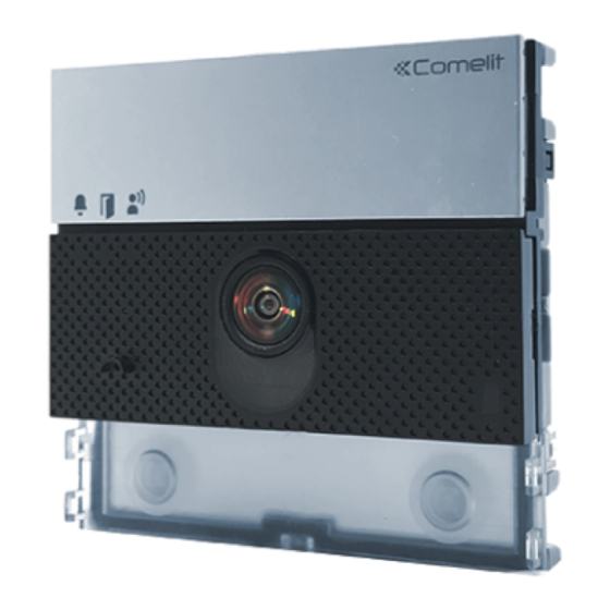
- Page 1 TECHNICAL MANUAL Audio/video module for Simplebus1 Ultra Art. UT1020 Simplebus1 Ultra remote camera audio module Passion.Technology.Design. Art. UT1010VC...
-
Page 2: Warning
• any purpose other than the intended use, • failure to observe the indications and warnings contained in this Manual / Instruction sheet. Comelit Group S.p.A. reserves the right to change the information provided in this Manual / Instruction Sheet at any time and without prior notice. -
Page 3: Table Of Contents
Table of contents Warning .................... 2 Description ..................4 UT1020 ......................4 UT1010VC ....................4 Installation notes (Art. UT1020) ............6 Technical characteristics ..............7 Art. UT1020 ....................7 Art. UT1010VC ..................8 Installation ..................9 Flush-mounted installation composition table ........9 Surface-mounted installation composition table ........9 Flush-mounted installation ............ -
Page 4: Description
Description UT1020 Audio/video module for Ultra entrance panel, Simplebus1 system. For use in systems with power supply unit art.1595 and art. 4888C. Wide-angle colour video camera (field of vision: 120° horizontal, 90° vertical) UT1010VC Audio module designed for connection of an analogue remote camera with PAL standard for Ultra entrance panel, Simplebus1 system. - Page 5 4. 5. 6. 14. 15. Art. UT1010VC 1. Indicator LEDs 13. Terminal block for connection: call sent (green) / system busy (red) RTE programmable RTE (local lock-release input) or DO input (door open indication) lock-release enabled GND RTE or DO input reference negative SE door lock reference negative audio enabled NO NC COM relay contacts...
-
Page 6: Installation Notes (Art. Ut1020)
Installation notes (Art. UT1020) 90° 175 cm 120° The camera must not be installed in front of light sources, or in places where the filmed subject is against the light. In dim environments, we recommend additional lighting is provided. -
Page 7: Technical Characteristics
Technical characteristics Art. UT1020 GENERAL DATA Type Modular Product height (mm) Product width (mm) Product depth (mm) Product weight (g) Product colour Black RAL9005, Transparent, Aluminium Material Polycarbonate, Aluminium alloy Flush mounting Yes, with specific accessory Surface mounting Yes, with specific accessory COMPATIBLE SYSTEMS Simplebus 2 audio/video with power supply unit art. -
Page 8: Art. Ut1010Vc
Art. UT1010VC GENERAL DATA Type Modular Product height (mm) Product width (mm) Product depth (mm) Product weight (g) Product colour Black RAL9005, Transparent, Aluminium Material Polycarbonate, Aluminium alloy Flush mounting Yes, with specific accessory Surface mounting Yes, with specific accessory COMPATIBLE SYSTEMS Simplebus 2 audio/video with power supply unit art. -
Page 9: Installation
Installation The entrance panel is available in flush-mounted or surface-mounted variants: Flush-mounted installation composition table 3110/1 3110/2 3110/3 3110/4 UT9181 UT9182 UT9183 UT9186 UT9189 UT9184 UT9188 A = Flush-mounted box B = Rain shield C = Flush-mounted module UT9161 UT9162 UT9163 UT9164 holder with finishing frame... -
Page 10: Flush-Mounted Installation
Flush-mounted installation Optional Optional BLACK... -
Page 11: Removing Nameplates (2A) / Module (2B)
CLACK! CLACK! CLACK! CLACK! CLACK! CLACK! The button has a nameplate which can be written on (A); alternatively, an adhesive label can be applied (B). MAX 0,2 mm The total thickness of the nameplate + adhesive label must not exceed 0.2 mm. You can visit the website pro.comelitgroup.com to download MAX 0,2 mm the PDF to print the entrance panel name cards, using the... -
Page 12: Installation With Side-By-Side Boxes
Installation with side-by-side boxes Before installing the boxes in the wall, fit the spacers. -
Page 13: Wall-Mounted Installation
Wall-mounted installation Optional Optional BLACK... -
Page 14: Removing Nameplates (2A) / Module (2B)
CLACK! CLACK! CLACK! CLACK! CLACK! CLACK! The button has a nameplate which can be written on (A); alternatively, an adhesive label can be applied (B). MAX 0,2 mm The total thickness of the nameplate + adhesive label must not exceed 0.2 mm. MAX 0,2 mm You can visit the website pro.comelitgroup.com to download the PDF to print the entrance panel name cards, using the... -
Page 15: Installation With Side-By-Side Boxes
Installation with side-by-side boxes... -
Page 16: Connections
Connections Connections for UT1020, UT1010VC 4888C 1595 120-230 V SE NO NC UT1020 UT1010VC Max 20 m. Local door-opener button. Variants Variant for using the outdoor entrance panel relay Variant for using a safety door lock 4888C 1595 4888C 1595 12/24V AC/DC 120-230 V 120-230 V... -
Page 17: Remote Camera Connection (Art. Ut1010Vc Only)
Remote camera connection (Art. UT1010VC only) 4888C 1595 120-230 V BLACK SE NO NC UT1010VC BLACK Max 20 m. Local door-opener button. -
Page 18: Module Connection
Module connection Connection of button modules Art. UT9200 4888C 1595 120-230 V BLACK SE NO NC UT1020 UT1010VC UT9200 Max 20 m. Local door-opener button. Connection of Touch-screen module Art. UT9270 4888C 1595 120-230 V SE NO NC UT1020 UT1010VC UT9270 Max 20 m. -
Page 19: Connection Of Numeric Keypad Module Art. Ut9279M
Connection of numeric keypad module Art. UT9279M 4888C 1595 120-230 V SE NO NC UT1020 UT1010VC UT9279M Max 20 m. Local door-opener button. -
Page 20: Programming
Programming For correct programming, follow the instructions below in order Configure button type Address button modules III. Program call addresses Configure button type (single/dual) DIP 6: configuring button type: Single button (DIP6 ON). default Dual button (DIP6 OFF, default). DIP 6: configuring button type: Single button (DIP6 ON). -
Page 21: Smart Programming Of Consecutive Addresses
Smart programming of consecutive addresses Make sure the button configuration (single/dual) is correct before proceeding with programming (see “Configure button type (single/dual)”) S1 S2 Take note of the DIP-switch settings Set the address of the apartment you wish 1 2 3 4 to call (for example: 1) example: using the DIP-... -
Page 22: Programming Of Specific Addresses
Programming of specific addresses Make sure the button configuration (single/dual) is correct before proceeding with programming (see “Configure button type (single/dual)”) S1 S2 Take note of the DIP-switch settings Set the address of the apartment you wish to 1 2 3 4 call (for example: 25) example: using the DIP-... -
Page 23: Special Programming Via Dip-Switch
Special programming via DIP-switch S1 S2 Take note of the DIP-switch settings 1. Set the dip switches in accordance with the function you wish to program (see table). 2. Press the confirm button. S1 S2 When programming is complete, make sure the button configuration is correct (single/dual), see Reset the configuration of the... -
Page 24: Special Programming Table
Special programming table CODE DIP SWITCHES ON FUNCTIONS Audio-visual messages 1,2,7,8 Hebrew 3,7,8 Polish 1,3,7,8 Catalan 2,3,7,8 Galician 1,2,3,7,8 Basque 2,3,4,7,8 Danish 1,2,3,4,7.8 Norwegian 1,2,5,7,8 Swedish 1,2,3,5,7.8 Italian 4,5,7,8 French 1,4,5,7,8 Spanish 2,4,5,7,8 Dutch 1,2,4,5,7.8 Greek 3,4,5,7,8 English 1,3,4,5,7.8 German 2,3,4,5,7.8 Portuguese 2,4,7,8... - Page 25 2,3,4,6,7.8 Self activation: disabled 2,4,5,8 System busy signalling time: 10 sec (default) 1,2,4,5,8 System busy signalling time: 300 sec 1,2,3,4,6,7,8 Confirmation tone on user call = enabled (default) 5,6,7,8 Confirmation tone on user call = disabled 1,2,5,6,7.8 Reset wait time (after hang-up or after lock-release): 10 sec (default) 3,5,6,7,8 Reset wait time (after hang-up or after lock-release): 1 sec 5,7,8...
-
Page 26: Twilight Sensor
Twilight sensor Camera LED lighting and button backlighting management The twilight sensor is in AUTO mode by default: the camera and button LEDs light up at night and switch off during the day. To change the setting to ON (LEDs always on) or OFF (LEDs always off), proceed as follows: S1 S2 Take note of the DIP-switch... -
Page 27: Checking Twilight Sensor Operation
Checking twilight sensor operation S1 S2 S1 S2 5 sec If it is daytime and you want to check AUTO mode operation for the twilight sensor, you can proceed as follows: 1. Enter programming mode 2. Block the twilight sensor for 5 seconds »... -
Page 28: Adjusting The Brightness Of The Button Leds And The Camera Light
Adjusting the brightness of the button LEDs and the camera light S1 S2 Take note of the DIP-switch settings Enable brightness control (A) for the camera (code 171) cod. 171 (B) for the buttons (code 161) 1 2 3 4 Set the desired function (code 171/161) and press the confirm cod. -
Page 29: Light-Me Function
S1 S2 When programming is complete, make sure the button configuration is correct (single/dual), see Reset the configuration of the “Configure button type DIP-switches (single/dual)”) Light-me function Thanks to this function, button backlighting is only enabled on the user’s request, by pressing the LIGHT-ME button on the audio/video module;... -
Page 30: Replacing The Audio/Video Module With Programming Restore Backup
Replacing the audio/video module with programming restore backup If the audio or audio/video module is replaced, the following instructions must be observed. The procedure should be completed within one hour of removal of the old module. Take note of the DIP-switch settings 1. -
Page 31: Configuring Via Pc
Configuring via PC All device configurations can be performed via PC and ViP Manager configuration software, available to download free of charge from pro.comelitgroup.com. √ You will need a USB micro-USB cable. Errors and indications INDICATION SOLUTION Line short-circuit Check connections Remove jumper J4 on the audio/video Dual power supply present module... -
Page 32: Addressing Table
Addressing table Dip switch Code 1,2,3,4,5 1,3,4,5,6 1,2,4,5,7 1,4,5,6,7 1,2,3,5,8 1,3,5,6,8 1,2,5,7,8 2,3,4,5,6 3,4,5,7 2,4,5,6,7 4,5,8 2,3,5,6,8 3,5,7,8 1,2,3,4,5.6 1,3,4,5,7 1,2,4,5,6.7 1,4,5,8 1,2,3,5,6.8 1,3,5,7,8 2,3,4,5,7 3,4,5,6,7 2,4,5,8 4,5,6,8 2,3,5,7,8 1,2,6 1,2,3,4,5.7 1,3,4,5,6.7 1,2,4,5,8 1,4,5,6,8 1,2,3,5,7.8 2,3,4,5,6.7 3,4,5,8 2,4,5,6,8 4,5,7,8 1,2,3 1,3,6 1,2,7 1,6,7... - Page 33 C E R T I F I E D M A N A G E M E N T S Y S T E M S w w w . c o m e l i t g r o u p . c o m Via Don Arrigoni, 5 - 24020 Rovetta (BG) - Italy...
Need help?
Do you have a question about the Simplebus1 Ultra UT1020 and is the answer not in the manual?
Questions and answers