norbar PNEUTORQUE STANDARD Series Operator's Manual
Stall tools
Hide thumbs
Also See for PNEUTORQUE STANDARD Series:
- Operator's manual (23 pages) ,
- Operator's manual (23 pages)

Related Manuals for norbar PNEUTORQUE STANDARD Series


Summary of Contents for norbar PNEUTORQUE STANDARD Series
- Page 1 OPERATOR’S MANUAL ® PNEUTORQUE STANDARD & SMALL DIAMETER SERIES STALL TOOLS Part Number 34317 | Issue 4 | Original Instructions (English)
-
Page 3: Table Of Contents
CONTENTS Part Numbers Covered by this Manual Safety Introduction Parts Included Accessories Features and Functions Set up Instructions Pneumatic Connections Lifting Handle Torque Reaction Setting Forward/Reverse Setting Torque for Fastener Tightening Setting Torque for Fastener Loosening Operating Instructions Tightening Releasing Maintenance Reaction Plate Air Lubrication... -
Page 4: Part Numbers Covered By This Manual
Note A 250000 N∙m PT 18 16054 16054.MTS Note A 300000 N∙m NOTE A: The output drive and reaction components must be engineered specifically for each customer application. Consult Norbar. Model Part Number Maximum (Small Diameter Square Automatic Torque Single Speed... -
Page 5: Safety
SAFETY IMPORTANT: DO NOT OPERATE THE TOOL BEFORE READING THESE INSTRUCTIONS. FAILURE TO DO SO MAY RESULT IN PERSONAL INJURY OR DAMAGE TO THE TOOL. This tool is intended for use with threaded fasteners. Any other use is not recommended. The use of ear protectors is recommended. -
Page 6: Introduction
All tools include Operators Manual (Part number 34317), Calibration Certificate & Air pressure graph (Part number 34208) NOTE A: The output drive and reaction components must be engineered specifically for each customer application. Consult Norbar. Accessories Nose Extensions 6” Nose Extension (¾” drive) 16480.006... -
Page 7: Features And Functions
FEATURES AND FUNCTIONS Replaceable Drive Square To avoid internal damage (especially due to torque overload), the output drive square has been designed to shear first. Tools are fitted with a drive square that can easily be replaced, alternative drive sizes are also available. -
Page 8: Set Up Instructions
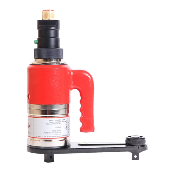
SET UP INSTRUCTIONS Pneumatic Connections WARNING: TO AVOID HAZARD FROM WHIPPING AIR HOSES MAKE ALL CONNECTIONS TO THE TOOL BEFORE TURNING ON THE AIR SUPPLY. Handle (H) Output Square Drive (D) Air Inlet (A) Trigger (J) Forward/Reverse Collar (C) Air Motor Air Exhaust Housing (F) Silencer (E) -
Page 9: Torque Reaction
Torque Reaction ® When the Pneutorque is in operation the reaction arm rotates in the opposite direction to the output drive square and must be allowed to rest squarely against a solid object or surface adjacent to the bolt to be tightened. - Page 10 It is essential the reaction plate rests squarely against a solid object or surface adjacent to the fastener to be tightened. The contact area must be within the shaded area of Figure 8, with the contact area as large as possible.
-
Page 11: Setting Forward/Reverse
Setting Forward / Reverse All tools are fitted with a direction collar, see Figure 11. FIGURE 11 – Collar for FWD, OFF or REV operation Rotate collar to select ‘FWD’ for forward (clockwise), ‘REV’ for reverse (anti-clockwise) or ‘OFF’. WARNING: FAILURE TO FULLY ENGAGE THE FORWARD/REVERSE COLLAR WILL RESULT IN DAMAGE TO THE SELECTOR VALVE. -
Page 12: Operating Instructions
OPERATING INSTRUCTIONS WARNING: KEEP HANDS CLEAR OF THE REACTION ARM. WARNING: WHEN USING THIS TOOL IT MUST BE SUPPORTED AT ALL TIMES IN ORDER TO PREVENT UNEXPECTED RELEASE IN THE EVENT OF FASTENER OR COMPONENT FAILURE. WARNING: CHANGING THE AIR PRESSURE AFTER SETTING THE PRESSURE REGULATOR WILL CHANGE THE STALL TORQUE VALUE. - Page 13 Press the trigger in short bursts to bring the reaction arm into contact with the reaction point. Fully press the trigger and keep fully depressed until tool stalls then release the trigger. Set speed selector to ‘SLOW’. NOTE: The air pressure calibration graph is only correct in the ‘SLOW’ setting. 10.
-
Page 14: Releasing
Releasing ® Fit Pneutorque with the correct size impact or high quality socket. Ensure the Forward / Reverse collar is correctly set (in ‘REV’ for right hand threads). Rotate tool and reaction arm into a convenient position. Fit the tool onto the fastener. Locate reaction arm adjacent to the reaction point. -
Page 15: Maintenance
Any other maintenance or repairs should be carried out by Norbar or a Norbar approved agent and should form part of a service. Service intervals will depend on the type of usage of the tools and the environment in which they are being used. -
Page 16: Drive Square
Drive Square To avoid internal damage (especially due to torque overload), the output drive square has been designed to shear first. This saves major internal damage and allows easy square removal. FIGURE 15 – Drive square fixing (left to right): Pin, Carrier Assembly , Screw and circlip. Square Drive Square Screw Torque... -
Page 17: Specifications
SPECIFICATIONS General Repeatability: ± 5%. Air Supply: Maximum pressure 6.0 bar (For maximum torque capacity). Air consumption 19 litres / sec (40 ft³/m [CFM]). Recommended Lubrication: Shell Tellus S2M 32 for the Lubro Control Unit. Temperature Range: 0°C to +50°C (operating). -20°C to +60°C (storage). Maximum Operating Humidity: 85% Relative Humidity at 30°C. -
Page 18: Standard Series
Standard Series Weight (kg) Free Speed Torque (At maximum air pressure) Tool Model Reaction Single Single MTS / Minimum Maximum MTS / AUT speed speed 160 N∙m 680 N∙m PT 1 30 rev/min 150 rev/min 10.6 14.1 (120 lbf∙ft) (500 lbf∙ft) 270 N∙m 1200 N∙m PT 1A... - Page 19 FIGURE 17 – Standard series tool (smaller) FIGURE 18 – Standard series tool (larger) Dimensions (mm) C minimum C maximum Model Single Single speed MTS / AUT speed PT 1 (¾”) PT 1 (1”) PT 1A PT 2 PT 5 PT 6 PT 7 PT 9...
-
Page 21: Trouble Shooting
TROUBLE SHOOTING The following is only a guide, for more complex faults please contact your local Norbar distributor or Norbar directly. Problem Likely Solutions Check air supply is functioning & connected. Check air pressure setting (at least 1 bar). Check correct setting of direction knob. - Page 22 NOTES...
- Page 23 Tel + 61 (0)8 8292 9777 Tel + 86 21 6145 0368 Email enquiry@norbar.com.au Email sales@norbar.com.cn NORBAR TORQUE TOOLS INC NORBAR TORQUE TOOLS INDIA PVT. LTD 36400 Biltmore Place, Willoughby, Plot No A-168, Khairne Industrial Area, Ohio, 44094 Thane Belapur Road, Mahape, Navi Mumbai –...
Need help?
Do you have a question about the PNEUTORQUE STANDARD Series and is the answer not in the manual?
Questions and answers