norbar PNEUTORQUE STANDARD Series Operator's Manual
Stall tools
Hide thumbs
Also See for PNEUTORQUE STANDARD Series:
- Operator's manual (23 pages) ,
- Operator's manual (23 pages)

Related Manuals for norbar PNEUTORQUE STANDARD Series


Summary of Contents for norbar PNEUTORQUE STANDARD Series
- Page 1 OPERATOR’S MANUAL PNEUTORQUE ® STANDARD SERIES STALL TOOLS Part Number 34317 | Issue 5 | Original Instructions (English)
-
Page 2: Table Of Contents
CONTENTS Part Numbers Covered by this Manual Safety General Safety Rules Projectile Hazards Entanglement Hazards Operating Hazards Repetitive Motions Hazards Accessory Hazards Workplace Hazards Dust and Fume Hazards Noise Hazards Vibration Hazards Additional Safety Instructions for Pneumatic Power Tools PneuTorque Specific Safety Instructions ®... -
Page 3: Part Numbers Covered By This Manual
Note A 300,000 N∙m NOTE A: The output drive and reaction components must be engineered specifically for each customer application. Consult Norbar. PneuTorque Standard series tools are also supplied in a ‘remote’ form without a handle. These are given a ®... -
Page 4: Safety
SAFETY IMPORTANT: THIS OPERATOR’S MANUAL SHOULD BE KEPT FOR FUTURE REFERENCE. General Safety Rules: • For multiple hazards, read and understand the safety instructions before installing, operating, repairing, maintaining, changing accessories on, or working near the assembly power tool for threaded fasteners. Failure to do so can result in serious bodily injury. -
Page 5: Repetitive Motions Hazards
Maintain a balanced body position and secure footing. • Release the trigger in the case of an interruption of the energy supply. • • Use only lubricants recommended by the manufacturer. • Do not use in confined spaces and beware of crushing hands between tool and workpiece. Repetitive Motions Hazards: When using a power tool for threaded fasteners, the operator can experience discomfort in the hands, •... -
Page 6: Noise Hazards
Noise Hazards: Unprotected exposure to high noise levels can cause permanent, disabling, hearing loss and other • problems, such as tinnitus (ringing, buzzing, whistling or humming in the ears). Therefore a risk assessment and implementation of appropriate controls for these hazards are essential. Appropriate controls to reduce the risk may include actions such as damping materials to prevent •... -
Page 7: Pneutorque ® Specific Safety Instructions
This tool is intended for use with threaded fasteners. Other uses within the limits of the tool may be • appropriate. Please contact Norbar for guidance. The user (or the user’s employer) shall assess the specific risks that can be present as a result of each •... -
Page 8: Introduction
All tools include Operators Manual (Part number 34317), Calibration Certificate & Air pressure graph (Part number 34208) NOTE A: The output drive and reaction components must be engineered specifically for each customer application. Consult Norbar. Accessories Nose Extensions 6” Nose Extension (¾” drive) 16480.006... -
Page 9: Features And Functions
FEATURES AND FUNCTIONS Replaceable Drive Square To avoid internal damage (especially due to torque overload), the output drive square has been designed to shear first. Tools are fitted with a drive square that can easily be replaced, alternative drive sizes are also available. -
Page 10: Set Up Instructions
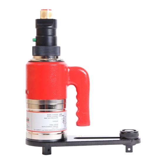
SET UP INSTRUCTIONS Pneumatic Connections WARNING: TO AVOID HAZARD FROM WHIPPING AIR HOSES MAKE ALL CONNECTIONS TO THE TOOL BEFORE TURNING ON THE AIR SUPPLY. Handle (H) Output Square Drive (D) Air Inlet (A) Reaction Plate (B) Trigger (J) Forward/Reverse Air Exhaust Collar (C) Silencer (E) -
Page 11: Torque Reaction
Torque Reaction When the PneuTorque is in operation the reaction arm rotates in the opposite direction to the output drive ® square and must be allowed to rest squarely against a solid object or surface adjacent to the bolt to be tightened. - Page 12 It is essential the reaction plate rests squarely against a solid object or surface adjacent to the fastener to be tightened. The contact area must be within the shaded area of Figure 6, with the contact area as large as possible.
-
Page 13: Setting Forward/Reverse
Setting Forward / Reverse All tools are fitted with a direction collar, see Figure 9. FIGURE 9 – Collar for , or operation Rotate collar to select for forward (clockwise), for reverse (anti-clockwise) or for off. WARNING: FAILURE TO FULLY ENGAGE THE FORWARD/REVERSE COLLAR WILL RESULT IN DAMAGE TO THE SELECTOR VALVE. -
Page 14: Operating Instructions
OPERATING INSTRUCTIONS WARNING: KEEP HANDS CLEAR OF THE REACTION ARM. WARNING: WHEN USING THIS TOOL IT MUST BE SUPPORTED AT ALL TIMES IN ORDER TO PREVENT UNEXPECTED RELEASE IN THE EVENT OF FASTENER OR COMPONENT FAILURE. WARNING: BEFORE USING TOOL, WEAR SUITABLE PPE, INCLUDING SAFETY SHOES, EYE PROTECTION, GLOVES AND OVERALLS. - Page 15 Release the ‘trigger’ and turn Collar to ‘OFF’. Remove tool from fastener. Manual Two Speed (Part Number “*****.MTS”) NOTE: ‘FAST’ speed is for initially running up of the fastener and ‘SLOW’ speed for applying the final torque. Set speed selector to ‘FAST’. FIGURE 10 –...
-
Page 16: Releasing
Releasing Fit PneuTorque with the correct size impact or high quality ® socket. Ensure the Forward / Reverse collar is correctly set (in for right hand threads). Rotate tool and reaction arm into a convenient position. Fit the tool onto the fastener. Locate reaction arm adjacent to the reaction point. -
Page 17: Maintenance
Any other maintenance or repairs should be carried out by Norbar or a Norbar approved agent and should form part of a service. Service intervals will depend on the type of usage of the tools and the environment in which they are being used. -
Page 18: Drive Square
Drive Square To avoid internal damage (especially due to torque overload), the output drive square has been designed to shear first. This saves major internal damage and allows easy square removal. FIGURE 13 – Drive square fixing (left to right): Pin, Carrier Assembly, Screw and circlip. Square Drive Square Screw Torque... -
Page 19: Specifications
SPECIFICATIONS General Repeatability: ± 5%. Air Supply: Maximum pressure 6.0 bar (For maximum torque capacity). Air consumption 19 litres / sec (40 ft³/m [CFM]). Recommended Lubrication: Fuchs Silkair VG22 or Shell Tellus S2 VX15 for the Lubro Control Unit. Temperature Range: 0°C to +50°C (operating). - Page 20 FIGURE 14 – Standard series tool (smaller) FIGURE 15 – Standard series tool (larger) Dimensions (mm) C minimum C maximum Model Single Single speed MTS / AUT speed PT 1 (¾”) PT 1 (1”) PT 1A PT 2 PT 5 PT 6 PT 7 PT 9...
-
Page 22: Trouble Shooting
TROUBLE SHOOTING The following is only a guide, for more complex faults please contact your local Norbar distributor or Norbar directly. Problem Likely Solutions Check air supply is functioning & connected. Check air pressure setting (at least 1 bar). Tool output does not rotate when trigger pushed. - Page 23 Tel + 61 (0)8 8292 9777 Tel + 86 21 6145 0368 Email enquiry@norbar.com.au Email sales@norbar.com.cn NORBAR TORQUE TOOLS INC NORBAR TORQUE TOOLS INDIA PVT. LTD 36400 Biltmore Place, Willoughby, Plot No A-168, Khairne Industrial Area, Ohio, 44094 Thane Belapur Road, Mahape, Navi Mumbai –...
Need help?
Do you have a question about the PNEUTORQUE STANDARD Series and is the answer not in the manual?
Questions and answers