Table of Contents
Advertisement
Advertisement
Table of Contents

Related Manuals for PO Fung Electronic UV-5R Pro


Summary of Contents for PO Fung Electronic UV-5R Pro
- Page 1 Analog UHF/VHF Two Way Radio Operating Manual Draft version...
- Page 2 PREFACE Thank you for purchasing UV-5R Pro Two Way Radio, which is a dual band/dual display radio/dual watch. This easy-to-use radio will deliver you secure, instant and reliable communications at peak efficiency. Please read this manual carefully before use. The information presented herein will help you to derive maximum performance from your radio.
-
Page 3: Table Of Contents
Table of Contents 1. GETTING STARTED 1.1 Regulations and Safety Warnings 1.2 Main features 1.3 Content of the packaging 2. BATTERY INFORMATION 2.1 Charging the Battery Pack 2.2 Charger Supplied 2.3 Use Caution with the Li-ion Battery 2.4 How to Charge 2.5 LED Indicator 2.6 How to Store the Battery 3. - Page 4 5.5 Frequency (VFO) mode 5.6 Channel (MR) mode 6. ADVANCED FEATURES 6.1 Frequency scanning 6.2 Channel scanning 6.3 Search CTCSS/DCS Code 6.4 Cursor▼▲Conversion (A/B) 6.5 High/low power fast selection 6.6 Keypad lock 6.7 FM Radio (FM) 6.8 Flashlight 6.9 1000Hz, 1450Hz, 1750Hz Tone-burst 6.10 Manual Programming (Channels Memory) 6.11 Repeaters Programming 7.
-
Page 5: Getting Started
1. GETTING STARTED 1.1 Regulations and Safety Warnings This device complies with Part 15 of the FCC Rules. Operation is subject to the following two conditions: (1) This device may not cause harmful interference. (2) This device must accept any interference received, including interference that may cause undesired operation. Important: Any changes or modifications not expressly approved by the party responsible for compliance could void the user's authority to operate this device. - Page 6 RF Exposure Information WARNING! Read this information before using the radio. In August 1996 the Federal Communications Commission (FCC) of the United States with its action in Report and Order FCC 96-326 adopted an updated safety standard for human exposure to radio frequency electromagnetic energy emitted by FCC regulated transmitters.
- Page 7 Hazardous Electromagnetic Fields-RF and Microwave. The information listed above provides the user with the information needed to make him or her aware of RF exposure, and what to do to as-sure that this radio operates with the FCC RF exposure limits of this radio. Electromagnetic Interference/Compatibility During transmissions, Our radio generates RF energy that can possibly cause interference with other devices or systems.
- Page 8 could impair call quality, damage the radio, or result in violation of FCC regulations. Do not use the radio with a damaged antenna. If a damaged antenna comes into contact with the skin, a minor burn may result. Please contact your local dealer for a replacement antenna.
- Page 9 Precautions for Portable Terminals ■ Operating Prohibitions To protect you against any property loss, bodily injury or even death, be sure to observe the following safety instructions: 1. Do not operate the product in a location containing fuels, chemicals, explosive atmospheres and other flammable or explosive materials.
- Page 10 To protect you against any property loss, bodily injury or even death, be sure to observe the following safety instructions: 1. Do not charge or replace your battery in a location containing fuels, chemicals, explosive atmospheres and other flammable or explosive materials. 2.
-
Page 11: Main Features
Contact your hauler for the local regulations and further information. 1.2 Main features • Frequency band: 150-174 & 400-480MHz • VHF and UHF bands and channel name displayed • Up to 128 memory channels • Squelch adjustable in 9 levels •... -
Page 12: Content Of The Packaging
1.3 Content of the packaging • 1 UV-5R Pro transceiver • 1 Li-Ion battery pack 1800mAh 7.4V • 1 Fast desktop charger • 1 Wall adaptor • 1 Antenna • 1 Belt clip If any item is missing, please verify with your dealer. -
Page 13: How To Charge
range may not fully charge the battery. c. Please turn off the radio before inserting it into the charger. It may otherwise interfere with correct charging. d. To avoid interfering with the charging cycle, please do not cut off the power or remove the battery during charging until the green light is on. -
Page 14: Led Indicator
2.5 LED Indicator STATUS No Battery Green and red alternately flashing Charge Normally Fully Charged Green Trouble Red blinks fast for a long time NOTE:Trouble means battery too warm, battery short-circuited or charger short-circuited. 2.6 How to Store the Battery a. -
Page 15: Installation Of Accessories
3. INSTALLATION OF ACCESSORIES Before the radio is ready for use we need to attach the antenna and battery pack, as well as charge the battery. 3.1 Installing/ Removing the Antenna a. Installing the Antenna: Screw the antenna into the connector on the top of the transceiver by holding the antenna at its base and turning it clockwise until secure. -
Page 16: Installing The Battery Pack
b. Removing the Belt Clip: Unscrew counter-clockwise to remove the belt clip. 3.3 Installing the battery pack Before attaching or removing the battery make sure your radio is turned off by turning the power/volume knob all the way counter-clockwise. a. Make sure the battery is aligned in parallel with the radio body with the lower edge of the battery about 1-2cm below the edge of the radio. -
Page 17: Additional Speaker/Microphone (Optional)
Remove the battery pack To remove the battery, press the battery release above the battery pack, as you slide the battery downward. 3.4 Installing the Additional Speaker/Microphone (Optional) Pry open the rubber MIC-Headset jack cover and then insert the Speaker / Microphone plug into the double jack. -
Page 18: Radio Overview
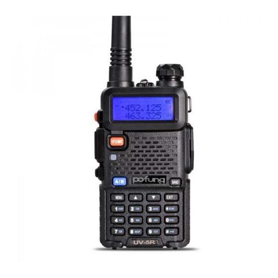
4. RADIO OVERVIEW 4.1 Buttons and controls of the radio... - Page 19 1. Antenna 2. Flashlight 3. Power / Switch / Volume control: Rotate to switch on/off the radio and adjust the volume 4. LCD display 5. Speaker 6. Microphone 7. Alphanumerical keypad 8. ▲/▼ keys: to select the functions/menu 9. EXIT: Push it to exit the menu and functions 10.
-
Page 20: Main Controls And Parts Of The Radio
4.2 Main controls and parts of the radio LCD Display 1. These symbols show that you set a DCS or CTCSS code in tx or rx. In tx mode it appears while you are transmitting, while in rx mode it is shown also in stand-by condition. 2. -
Page 21: Status Indications
15. Indicates the VFO in use and the current menu or function setting. This icon is displayed close to the band in use or to the menu settings. Battery Level Indicator When the battery level indicator reads the battery is depleted. At this point the radio will start beeping periodically as well as flash the backlight of the display and when voice prompts are enabled, a "Low Voltage"... - Page 22 becomes the active listening and transmit frequency or channel. To save frequencies to channel memory you must be on the A display. When listening to broadcast FM, the broadcast FM is 88-108 MHz band. • [MENU] key: it is used for activating the MENU, choose each MENU selection and confirm the parameter. •...
-
Page 23: Basic Operations
The Baofeng UV5R PRO features a battery voltage meter that the current voltage of the battery on the display. To see the voltage displayed, press and hold the [0SQL] key for about two seconds. • # If you press this button for more than 2 seconds you will lock/unlock the keypad. 5. -
Page 24: Channel Selection
press the [PTT] key, a call to the current channel. Speak into the microphone with normal tone. Initiate a call, the red LED is • Receive a call: When you release the [PTT] key, you can answer it without any action. When receiving a call, the green LED is on. -
Page 25: Channel (Mr) Mode
Just because you can program in a channel does not mean you're automatically authorized to use that frequency. Transmitting on frequencies you're not authorized to operate on is illegal, and in most jurisdictions a serious offence. If you get caught transmitting without a license you can and will get fined, and in worst case sent to jail. However, it is legal in most jurisdictions to listen. -
Page 26: Search Ctcss/Dcs Code
set. b. You can change the scanning direction with the ▲and ▼ keys. c. Press any key to stop scanning. Note: for Scan mode, see Menu No.18. 6.3 Search CTCSS/DCS Code With this function you can search and store the CTCSS/DCS code used by other radios. Procedure: a. -
Page 27: High/Low Power Fast Selection
▼ is displayed next to the channel. 6.5 High/low power fast selection In channel mode, press [# ] key to shift between high and low power. 6.6 Keypad lock This function locks the keypad to prevent accidental pressure of the controls. To unlock the keypad, press [# ] for more than 2 seconds. -
Page 28: Manual Programming (Channels Memory)
To send out a tone-burst; you simultaneously will press a key while holding down the PTT. No further configuration required using this feature. The following configurations will transmit accordingly: • [PTT] + [CALL] = Transmits 1000Hz Tone Burst • [PTT] + [VFO/MR] = Transmits 1450Hz Tone Burst •... - Page 29 TX = 457.000 MHz (This is a (+ 5) Offset) TX CTCSS tone 123.0 a. Change from Menu to Menu by pressing the [EXIT] key. b. Set radio to VFO Mode by pressing [VFO/MR] Channel number at the right will disappear. c.
-
Page 30: Repeaters Programming
e. Enter RX frequency (Ex. 456000) f. [MENU] [2][7] [MENU] [1][0] [MENU] Enter the desired channel (Ex 10) -->> [EXIT] Channel has been added g. [VFO/MR] Return to MR Mode. Channel number will re-appear. 6.11 Repeaters Programming The following instructions assume that you know what transmit and receive frequencies your repeater employs, and that you're authorized to use it. - Page 31 l. Press [EXIT] to exit the menu. If everything went well, you should be able to make a test call through the repeater. NOTE: If you're experiencing problems making a connection to the repeater, check your settings and/or go through the procedure again.
-
Page 32: Working The Menu System
7. WORKING THE MENU SYSTEM For a complete reference on available menu items and parameters, see Appendix C, Shortcut Menu operations. Note: in channel mode, the setting of these features is not possible: CTCSS/ DCS tones, PTT-ID, Busy channel lock out, channel name edit. -
Page 33: Functions And Operations
b. Use the numerical keypad to enter the number of the menu item. c. To enter the menu item, press the [MENU] key. d. For entering the desired parameter you have two options: a). Use the arrow keys as we did in the previous section; or b). - Page 34 (4) Battery save (SAVE) - MENU No.3 The power save feature enables a reduction in the consumption of the battery when the radio is in standby. You have 5 selections available: OFF / 1:1 / 1:2 / 1:3 / 1:4. For example: 1:1 = 1s’...
- Page 35 The TOT function is used to prevent a too long transmission and limits the tx time: TOT temporarily stops the transmission if the radio has been used beyond the max pre-set time (for example 15s, 30s, 45s, etc). (11) Receiving DCS (R-DCS) - MENU No.10 DCS codes are similar to access codes and can be added to channels, so as to create a sort of personal channel.
- Page 36 Selects 1 of 15 DTMF codes. The DTMF codes are programmed with software and are up to 5 digits each. (19) SCAN Resume Mode (SC-REV) - MENU No.18 Thanks to this function, UV-5R PRO can SCAN in frequency or channel mode. You can choose amongst three options: TO: Time-operated SCAN Whenever a signal is detected, the radio will suspend the SCAN for 5 seconds, and then will continue to SCAN even if the signal is still present.
- Page 37 You can choose amongst 4 possibilities. • OFF: press PTT to turn it off • BOT: the code is sent when you press the PTT • EOT: the code is sent when the PTT is released • BOTH: the code is sent when you press and release the PTT Note: select ‘OFF’...
- Page 38 Note: Channel name mode must be set by the programming software. Up to three numbers or characters can be edited. (24) Busy Channel Lock (BCL) - MENU No. 23 When this function is on, it may prevent other radios’ interference. If the selected channel is being used by other radios, when you press key PTT, your radio cannot transmit.
- Page 39 When the radio is in frequency working mode or standby mode, input the desired frequency or parameters directly. To set a CTCSS tone or a DCS code in tx or rx on the stored channel, refer to paragraphs MENU 10-13 Note: You cannot overwrite a stored channel;...
- Page 40 • PURPLE • ORANGE (33) Alarm Mode (AL-MOD) - MENU No.32 This function can set the tone alarm/code alarm/site alarm of the radio. Keep pressed the [CALL] key for 3 seconds to start the alarm tone. The following three options can be selected: •...
- Page 41 452.5875 MHz and 155.550 MHz, but can transmit on 452.5875 MHz only. While if you choose option B, 155.550MHz is the tx frequency band and 452.5875MHz is the rx frequency band. In the upper VFO 452.5875 MHz will be displayed while the lower VFO will show 155.550 MHz; you can receive on both 452.5875 MHz and 155.550 MHz, but transmit on 155.550 MHz only.
- Page 42 With this function you have the confirmation that the repeater has transferred the signal. You can choose amongst: OFF 1,2,3,4,5,….10 to set the delay time. (39) Display mode at the turning on (PONMSG) Menu No.38 With this function you can set the display mode when the radio is turned on. Available options: •...
-
Page 43: Appendix A. - Trouble Shooting Guide
Appendix A. – Trouble shooting guide Phenomena Analysis Solution The battery may be installed improperly. Remove and reattach the battery. The battery power may run out. Recharge or replace the battery. You cannot turn on the radio. The battery may suffer from poor contact caused by Clean the battery contacts or replace the dirty or damaged battery contacts. -
Page 44: Appendix B. - Technical Specifications
Appendix B. - Technical Specifications General Frequency Range 150-174 & 400-480MHz (Tx) 136-174&400-520MHz (Rx) Memory Channel 128 Groups Operation Voltage DC 7.4 V ±10% Battery Capacity 1800mAh (Li-Ion) Frequency Stability ±2.5ppm Operating Temperature -20℃ to +50℃ Mode of Operation Simplex Antenna Impedance 50ohm Transmitter Part... -
Page 45: Appendix C. - Shortcut Menu Operations
Appendix C. - Shortcut Menu operations MENU Name Enter item LCD display Select able (Full Name) 0-9 Levels SQL - Squelch Level MENU+0 0:Lowest 9:Highest 2.5K/5.0K/6.25K/10.0K STEP –Step Frequency MENU+1 12.5K/20.0K/25.0K/50.0K OFF: SAVE - Battery Saving MENU+3 OFF, 1-9 OFF: off VOX - VOX MENU+4 1:Highest Sensitivity... - Page 46 BEEP - Keypad Beep MENU+8 *Allows audible confirmation of a key press. 15,30…600S *This feature provides a safety switch that limits transmission time to a programmed value. This will TOT- Time-Out-Timer MENU+9 promote battery conservation by not allowing you to make excessively long transmissions, and in the event of a stuck PTT switch it can prevent interference to other users as well as battery depletion...
- Page 47 67.0HZ…254.1HZ T-CTCS - Transmitter MENU+13 *Transmits a specific and continuous sub audible signal CTCSS to unlock the squelch of a distant receiver (usually a repeater). VOICE - Voice MENU+14 Reminding *Allows audible voice confirmation of a key press. ANI-ID -ANI-ID MENU+15 It can be programmed by software OFF: No DTMF Side Tones are heard...
- Page 48 OFF: No ID is sent BOT: The selected S-CODE is sent at the beginning PTT-ID - PTT-ID MENU+19 EOT: The selected S-CODE is sent at the ending BOTH : The selected S-CODE is sent at the beginning and ending 0,1,2…,50ms PTT-LT –...
- Page 49 OFF: TX = RX (simplex) SFT-D – Frequency MENU+25 +: TX will be shifted higher in frequency than RX Offset Direction - : TX will be shifted lower in frequency than RX 00.000…69.990 OFFSET -Frequency shift MENU+26 *Specifies the difference between the TX and RX amount frequencies 000…127...
- Page 50 SITE: Sounds alarm through your radio speaker only AL-MOD - Alarm Mode MENU+32 TONE: Sending alarm tone CODE: Sending alarm code VHF:144-148,UHF:430-450 (Canadian IC standard) VHF:144-146,UHF:430-440 (EU CE standard) BAND - Band Selection MENU+33 *In VFO/Frequency mode, sets [A] or [B] to the VHF or UHF band.
- Page 51 We do not guarantee, for any particular purpose, the accuracy, validity, timeliness, legitimacy or completeness of the third-party products and contents involved in this manual. PO FUNG ELECTRONIC (HK) INTERNATIOANL GROUP COMPANY Address: 3/F FULOK BLDG 131-133 WING LOK ST SHEUNG WAN, Hong Kong E-mail: sales@baofengradio.com...
Need help?
Do you have a question about the UV-5R Pro and is the answer not in the manual?
Questions and answers