Table of Contents
Advertisement
Available languages
Available languages
Quick Links
Advertisement
Chapters
Table of Contents

Related Manuals for Chauvin Arnoux PAC 15


Summary of Contents for Chauvin Arnoux PAC 15
- Page 1 FR - Notice de fonctionnement GB - User’s manual DE - Bedienungsanleitung IT - Manuale d’uso ES - Manual de instrucciones PAC 15 PAC 16 Pince ampèremétrique AC/DC AC/DC ammeter clamp AC/DC-Stromzange Pinza amperometrica AC/DC Pinza amperimétrica CA/CC...
- Page 2 Deutsch ........................42 Italiano ........................62 Español ........................82 Vous venez d’acquérir une pince ampèremétrique PAC 15 ou PAC 16 et nous vous remercions de votre confiance. Pour obtenir le meilleur service de votre pince : „ lisez attentivement cette notice de fonctionnement, „...
-
Page 3: Table Of Contents
1.1. État de livraison ........................4 1.2. Accessoire ........................... 4 1.3. Mise en place de la pile ....................... 5 1.4. Fonctionnalités ........................5 1.5. PAC 15 ..........................6 1.6. PAC 16 ..........................7 2. UTILISATION ..........................8 2.1. Mise en marche ........................8 2.2. -
Page 4: Présentation
1. PRÉSENTATION 1.1. ÉTAT DE LIVRAISON Les pinces PAC 15 et PAC 16 sont livrées dans une boîte en carton avec : „ une pile 9 V alcaline (type 6LF22, 6LR61 ou NEDA 1604), „ une notice de fonctionnement 5 langues, „... -
Page 5: Mise En Place De La Pile
1.4. FONCTIONNALITÉS Les pinces ampèremétriques PAC 15 et PAC 16 permettent de mesurer des courants continus jusqu’à 600 A, alternatifs jusqu’à 400 A efficace (600 A crête) ou mixtes (AC+DC), sans ouvrir le circuit dans lequel ils circulent. Elles restituent la forme et l’amplitude du courant mesuré sous la forme d’une tension. -
Page 6: Pac 15
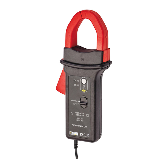
1.5. PAC 15 Bras fixe. 2 prises bananes mâles Ø 4 mm. Bras mobile. Flèche indiquant l e s e n s d u courant. Garde de protection. Gâchette. Bouton de réglage du zéro. Voyants. Zero Commutateur à glissière 2 positions. -
Page 7: Pac 16
1.6. PAC 16 Bras fixe. 2 prises bananes mâle Ø 4 mm. Bras mobile. Flèche indiquant l e s e n s d u courant. Garde de protection Gâchette. Bouton de réglage du zéro. Voyants. Zero Commutateur 10 mV/A à glissière 3 1 mV/A positions. -
Page 8: Utilisation
Allumez la pince en poussant le commutateur à glissière sur la position 1 mV/A ou sur la position 10 mV/A. La position 1 mV/A correspond au calibre 600 A pour les PAC 15 et PAC 16. La position 10 mV/A correspond au calibre 60 A pour les PAC 16. -
Page 9: Mise En Veille Automatique
10 mV/A 10 mV/A 10 mV/A 1 mV/A 1 mV/A 1 mV/A PAC 16 PAC 16 PAC 16 Par exemple, une lecture de 1 V sur l’appareil de mesure correspond à un courant de = 100 A 10 mV/A sur le calibre 600 A. 2.4. -
Page 10: Caractéristiques
3. CARACTÉRISTIQUES 3.1. CONDITION DE RÉFÉRENCE Grandeur d’influence Valeurs de référence Température 23 ± 5 °C Humidité relative 20 à 75 %HR Position du conducteur centré sur les repères de la pince Fréquence du signal mesuré DC à 65 Hz sinusoïdal Champ électrique extérieur Champ magnétique DC extérieur (champ terrestre) <... - Page 11 Courbe typique de l’erreur en amplitude à 60 Hz Erreur (%) Courant (A) 1000 Courbe typique de l’erreur en amplitude en DC Erreur (%) Courant (A) 1000 Courbe typique de l’erreur de phase à 60 Hz Déphasage (°) -0,5 Courant (A) -1,5 1000...
- Page 12 3.2.1. CARACTÉRISTIQUES EN FRÉQUENCE, SENSIBILITÉ 1 mV/A Bande passante à -3 dB : DC à 30 kHz Fréquence 50 Hz 400 Hz 1 kHz 10 kHz Impédance d'insertion < 0,01 mΩ 0,01 mΩ 0,12 mΩ 2,8 mΩ Courbe typique de l’erreur en amplitude à 100 A en fonction de la fréquence Erreur (%) Fréquence (Hz) 1 000...
-
Page 13: Caractéristiques Électriques, Sensibilité 10 Mv/A (Pac 16)
3.3. CARACTÉRISTIQUES ÉLECTRIQUES, SENSIBILITÉ 10 mV/A (PAC 16) Impédance de sortie : 215 W Domaine de mesure 0,5 à 30 Aac/dc 30 à 40 Aac/dc 40 à 60 Adc spécifié Incertitude intrinsèque ≤ ± (3%L + 5 mV) ≤ ± 1,5%L ≤... - Page 14 Courbe typique de l’erreur de phase à 60 Hz Déphasage (°) Courant (A) 3.3.1. CARACTÉRISTIQUES EN FRÉQUENCE Bande passante à -3 dB : DC à 30 kHz Fréquence 50 Hz 400 Hz 1 kHz 10 kHz Impédance d'insertion < 0,01 mΩ 0,01 mΩ...
-
Page 15: Limites De Fonctionnement
Courbe typique de l’erreur de phase à 100 A en fonction de la fréquence Déphasage (°) 0° -10° -20° -30° -40° -50° Fréquence (Hz) -60° 1 000 10 000 100 000 3.4. LIMITES DE FONCTIONNEMENT „ En courant continu : 3 000 A permanent „... -
Page 16: Variations Dans Le Domaine D'utilisation
3.5. VARIATIONS DANS LE DOMAINE D’UTILISATION Erreur en % de la lecture Grandeur d’influence Plage d’influence Typique Maximale Température ‑10 à + 55 °C 0,3 % Humidité relative 10 à 85%HR 0,5 % de 10 à 400 Hz Fréquence de 400 Hz à 7 kHz 3,5% de 7 à... -
Page 17: Conditions D'environnement
3.7. CONDITIONS D’ENVIRONNEMENT L’appareil doit être utilisé dans les conditions suivantes : °C 1 = Domaine de référence. 2 = Domaine d’utilisation. 3 = Domaine de stockage. Utilisation à l’intérieur. Degré de pollution Altitude < 2000 m Altitude de transport ≤ 12 000 m 3.8. -
Page 18: Conformité Aux Normes Internationales
3.8.1. PROTECTION PAR L’ENVELOPPE Indice de protection : „ IP 40 selon IEC 60529 „ IK 06 selon IEC 62262 Chute selon IEC 61010‑2‑032. 3.9. CONFORMITÉ AUX NORMES INTERNATIONALES L’appareil est conforme selon l’IEC 61010‑2‑032, 300 V catégorie IV ou 600 V catégorie III. Isolation double ou renforcée Type de capteur de courant selon l’IEC 61010-2-032 : type A 3.10. -
Page 19: Maintenance
4. MAINTENANCE Excepté la pile, l’appareil ne comporte aucune pièce susceptible d’être remplacée par un personnel non formé et non agréé. Toute intervention non agréée ou tout remplacement de pièce par des équivalences risque de compromettre gravement la sécurité. 4.1. NETTOYAGE Déconnectez tout branchement de la pince. - Page 20 de la position OFF jusqu’à la position du calibre à régler (1 mV/A ou 10 mV/A). Maintenez encore le bouton DC Zéro appuyé pendant 30 secondes jusqu'à ce que le voyant ON clignote en jaune puis en vert. Relâcher le bouton DC Zéro. La pince est en mode de réglage. 4.
-
Page 21: Garantie
5. GARANTIE Notre garantie s’exerce, sauf stipulation expresse, pendant 24 mois après la date de mise à disposition du matériel. Extrait de nos Conditions Générales de Vente, communiquées sur demande. La garantie ne s’applique pas suite à : „ une utilisation inappropriée de l’équipement ou à une utilisation avec un matériel incompatible ; „... - Page 22 The product is declared recyclable following an analysis of the life cycle in accordance with standard ISO 14040. Chauvin Arnoux has adopted an Eco‑Design approach in order to design this appliance. Analysis of the complete lifecycle has enabled us to control and optimize the effects of the product on the environment.
- Page 23 1.1. Delivery condition ......................24 1.2. Accessories ........................24 1.3. Inserting the battery ......................25 1.4. Functions .......................... 25 1.5. PAC 15 ..........................26 1.6. PAC 16 ..........................27 2. USE ...............................28 2.1. Getting started ........................28 2.2. Zero adjustment ........................ 28 2.3.
-
Page 24: Presentation
1. PRESENTATION 1.1. DELIVERY CONDITION PAC 15 and PAC 16 clamps are delivered in a cardboard box with: „ one 9V alkaline battery (type 6LF22, 6LR61, or NEDA 1604), „ one user manual in 5 languages, „ one multilingual safety data sheet, „... -
Page 25: Inserting The Battery
1.4. FUNCTIONS PAC 15 and PAC 16 ammeter clamps are used to measure DC currents up to 600A, AC currents up to 400Arms (600A peak), and combined AC+DC currents without opening the circuit in which the currents flow. They indicate the shape and amplitude of the current measured in the form of a voltage. -
Page 26: Pac 15
1.5. PAC 15 Fixed arm. 2 male banana plugs 4mm in diameter. Mobile arm. Arrow indicating the direction of current flow. Guard. Trigger. Zero adjustment button. Indicators. Zero Two-position slide switch. 1 mV/A 600 V CAT III 300 V CAT IV... -
Page 27: Pac 16
1.6. PAC 16 Fixed arm. 2 male banana plugs 4mm in Mobile arm. diameter. Arrow indicating the direction of current flow. Guard. Trigger. Zero adjustment button. Indicators. Zero Three-position 10 mV/A slide switch. 1 mV/A 600 V CAT III 300 V CAT IV 400 A AC 600 A DC AUTO POWER OFF... -
Page 28: Use
Switch the clamp on by pushing the slide switch to the 1mV/A or the 10mV/A setting. The 1mV/A setting corresponds to the 600A range of the PAC 15 or PAC 16. The 10mV/A setting corresponds to the 60A range of the PAC 16. -
Page 29: Automatic Standby
10 mV/A 10 mV/A 10 mV/A 1 mV/A 1 mV/A 1 mV/A PAC 16 PAC 16 PAC 16 For example, a reading of 1V on the measuring instrument corresponds to a current of = 100A 10 mV/A in the 600A range. 2.4. -
Page 30: Characteristics
3. CHARACTERISTICS 3.1. REFERENCE CONDITIONS Quantity of influence Reference values Temperature 23 ±5°C Relative humidity 20 to 75 %RH Position of the conductor centred on the marks on the clamp Frequency of the measured signal DC to 65Hz sine wave External electric field zero External DC magnetic field (earth's field) - Page 31 Typical amplitude error curve at 60Hz Error (%) Current (A) 1000 Typical amplitude error curve in DC Error (%) Current (A) 1000 Typical phase error curve at 60Hz Phase shift (°) -0,5 Current (A) -1,5 1000...
- Page 32 3.2.1. FREQUENCY CHARACTERISTICS, SENSITIVITY 1 MV/A Pass band to 3dB down: DC at 30kHz Frequency 50Hz 400Hz 1kHz 10kHz Insertion impedance < 0.01mΩ 0.01mΩ 0.12mΩ 2.8mΩ Typical amplitude error versus frequency curve at 100A Error (%) Frequency (Hz) 1 000 10 000 100 000 Typical phase versus frequency error curve at 100A...
-
Page 33: Electrical Characteristics, Sensitivity 10 Mv/A (Pac 16)
3.3. ELECTRICAL CHARACTERISTICS, SENSITIVITY 10 MV/A (PAC 16) Output impedance: 215 W Specified 0.5 to 30Aac/dc 30 to 40Aac/dc 40 to 60Adc measurement range Intrinsic uncertainty ≤±(3%R + 5mV) ≤±1.5%R ≤±1.5%R Phase error (45 to 65Hz) Specified measurement range 1 to 20Aac 20 to 40Aac Phase shift ≤‑3°... - Page 34 Typical phase versus frequency error curve at 60Hz Phase shift (°) Current (A) 3.3.1. FREQUENCY CHARACTERISTICS Pass band to 3dB down: DC at 30kHz Frequency 50Hz 400Hz 1kHz 10kHz Insertion impedance < 0.01 mΩ 0.01 mΩ 0.12 mΩ 2.8 mΩ Typical amplitude error versus frequency curve at 100A Error (%) Frequency (Hz)
-
Page 35: Operating Limits
Typical phase error versus frequency curve at 100A Phase shift (°) 0° -10° -20° -30° -40° -50° Frequency (Hz) -60° 1 000 10 000 100 000 3.4. OPERATING LIMITS „ In DC: 3000A permanent „ In AC: 1000A permanent up to 1kHz from 1kHz, Imax = 1000/f (kHz) „... -
Page 36: Variations In The Range Of Use
3.5. VARIATIONS IN THE RANGE OF USE Error in % of reading Quantity of influence Range of influence Typical Maximum Temperature ‑10 to + 55°C 0.3% Relative humidity 10 to 85%RH 0.5% from 10 to 400Hz Frequency from 400Hz to 7kHz 3.5% from 7 to 30kHz see curves... -
Page 37: Environmental Conditions
3.7. ENVIRONMENTAL CONDITIONS The device must be used in the following conditions: °C 1 = Range of reference. 2 = Operating range. 3 = Storage range. Indoor use. Degree of pollution Altitude < 2000 m Transport altitude ≤12.000 m 3.8. CONSTRUCTION SPECIFICATIONS Dimensions (LxWxH) 224x97x44mm Weight... -
Page 38: Conformity To International Standards
3.8.1. PROTECTION BY THE HOUSING Protection index: „ IP 40 per IEC 60529 „ IK 06 per IEC 62262 Drop test per IEC 61010‑2‑032. 3.9. CONFORMITY TO INTERNATIONAL STANDARDS The instrument is compliant with IEC 61010‑2‑032, 300V in category IV or 600V in category III. Double or reinforced insulation Type of current sensor per IEC 61010-2-032: type A 3.10. -
Page 39: Maintenance
4. MAINTENANCE Except for the battery, the instrument contains no parts that can be replaced by personnel who have not been specially trained and accredited. Any unauthorized repair or replacement of a part by an “equivalent” may gravely impair safety. 4.1. - Page 40 setting to the range to be adjusted (1mV/A or 10mV/A). Keep the DC Zero button pressed for 30 seconds, until the ON indicator blinks yellow, then green. Release the DC Zero button. The clamp is in the adjustment mode. 4. The clamp then performs an adjustment of the zero. 5.
-
Page 41: Warranty
5. WARRANTY Except as otherwise stated, our warranty is valid for 24 months starting from the date on which the equipment was sold. Extract from our General Conditions of Sale, provided on request. The warranty does not apply in the following cases: „... - Page 42 DEUTSCH Sie haben eine PAC 15 bzw. PAC 16 Stromzange erstanden, wir danken Ihnen für Ihr Vertrauen. Um die optimale Benutzung Ihres Gerätes zu gewährleisten, bitten wir Sie: „ diese Bedienungsanleitung sorgfältig zu lesen, „ und die Benutzungshinweise genau zu beachten.
- Page 43 1. VORSTELLUNG ..........................44 1.1. Lieferumfang ........................44 1.2. Zubehör ..........................44 1.3. Akku einlegen ........................45 1.4. Funktionsumfang ......................45 1.5. PAC 15 ..........................46 1.6. PAC 16 ..........................47 2. VERWENDUNG ...........................48 2.1. Inbetriebnahme ........................48 2.2. Nullpunkteinstellung ......................48 2.3.
-
Page 44: Vorstellung
„ Reparatur und messtechnische Überprüfung darf nur durch zugelassenes Fachpersonal erfolgen. 1. VORSTELLUNG 1.1. LIEFERUMFANG Die Srommesszangen PAC 15 und PAC 16 werden in einem Karton geliefert: „ eine 9V Alkalibatterie (6LF22, 6LR61, NEDA 1604), „ eine Bedienungsanleitung in 5 Sprachen, „... -
Page 45: Akku Einlegen
1.4. FUNKTIONSUMFANG Mit den PAC 15 und PAC 16 Stromzangen lässt sich Gleichstrom bis 600 A, Wechselstrom bis zu 400 A effektiv (600 A Spitze) und AC/DC‑Strom in Kabeln bestimmen, ohne den Stromkreis unterbrechen zu müssen. Sie stellen die Form und Amplitude des gemessenen Stroms in Form von Spannung dar. -
Page 46: Pac 15
1.5. PAC 15 Feste Backe 2 Bananenstecker Ø 4 mm. Bewegliche Backe Handschutz Pfeil als Stromrichtungsangabe Nullpunkteinstellung Trigger mit Taste Signallampen Zero 1 mV/A Zweistellungsschalter 600 V CAT III 300 V CAT IV 400 A AC 600 A DC AUTO POWER OFF... -
Page 47: Pac 16
1.6. PAC 16 Feste Backe 2 Bananenstecker Ø 4 mm. Bewegliche Backe Handschutz Pfeil als Stromrichtungsangabe Nullpunkteinstellung Trigger mit Taste Signallampen Zero 10 mV/A Dreistellungsschalter 1 mV/A 600 V CAT III 300 V CAT IV 400 A AC 600 A DC AUTO POWER OFF PAC 16 AC/DC CURRENT CLAMP... -
Page 48: Verwendung
Schalten Sie die Zange ein, indem Sie den Schiebeschalter auf Position 1 mV/A bzw. 10 mV/A stellen. Position 1 mV/A entspricht dem Messbereich 600 A für PAC 15 und PAC 16. Position 10 mV/A entspricht dem Messbereich 60 A für PAC 16. -
Page 49: Abschaltautomatik
10 mV/A 10 mV/A 10 mV/A 1 mV/A 1 mV/A 1 mV/A PAC 16 PAC 16 PAC 16 Ein Leswert von 1 V am Messgerät entspricht zum Beispiel einem Strom von = 100 A im Messbereich 10 mV/A 600 A~. 2.4. -
Page 50: Technische Daten
3. TECHNISCHE DATEN 3.1. REFERENZBEDINGUNGEN Einflussgröße Bezugswerte Temperatur 23 ± 5 °C Relative Luftfeuchte 20 bis 75 % RF mittig zwischen den Zentriermarken an der Leiterposition Zange Signalfrequenz des Messsignals DC bei 65 Hz sinusförmig Elektrische Feldstärke Null Magnetfeldstärke DC (Erdfeld) <... - Page 51 Typische Amplitudenabweichung bei 60 Hz Fehler (%) Strom (A) 1000 Typische Amplitudenabweichung in DC Fehler (%) Strom (A) 1000 Typische Phasenabweichung bei 60 Hz Phasenverschiebung (°) -0,5 Strom (A) -1,5 1000...
- Page 52 3.2.1. FREQUENZEIGENSCHAFTEN, EMPFINDLICHKEIT 1 MV/A Bandbreite bei -3 dB: DC bei 30 kHz Frequenz 50 Hz 400 Hz 1 kHz 10 kHz Eingangsimpedanz < 0,01 mΩ 0,01 mΩ 0,12 mΩ 2,8 mΩ Typische Amplitudenabweichung bei 100 A in Bezug auf die Frequenz Fehler (%) Frequenz (Hz) 1 000...
-
Page 53: Elektrische Spezifikationen, Empfindlichkeit 10 Mv/A (Pac 16)
3.3. ELEKTRISCHE SPEZIFIKATIONEN, EMPFINDLICHKEIT 10 MV/A (PAC 16) Ausgangsimpedanz: 215 W Angegebener 0,5 - 30 Aac/dc 30 - 40 Aac/dc 40 - 60 A dc Messbereich Eigenunsicherheit ≤ ± (3%L + 5 mV) ≤ ± 1,5%L ≤ ± 1,5%L Phasenfehler (45 bis 65 Hz) Angegebener Messbereich 1 - 20 Aac 20 - 40 Aac... - Page 54 Typische Phasenabweichung bei 60 Hz Phasenverschiebung (°) Strom (A) 3.3.1. FREQUENZEIGENSCHAFTEN Bandbreite bei -3 dB: DC bei 30 kHz Frequenz 50 Hz 400 Hz 1 kHz 10 kHz Eingangsimpedanz < 0,01 mΩ 0,01 mΩ 0,12 mΩ 2,8 mΩ Typische Amplitudenabweichung bei 100 A in Bezug auf die Frequenz Fehler (%) Frequenz (Hz) 1 000...
-
Page 55: Grenze Der Betriebsbedingungen
Typische Phasenabweichung bei 100 A in Bezug auf die Frequenz Phasenverschiebung (°) 0° -10° -20° -30° -40° -50° Frequenz (Hz) -60° 1 000 10 000 100 000 3.4. GRENZE DER BETRIEBSBEDINGUNGEN „ Gleichstrombetrieb: 3 000 A Dauerbetrieb „ Wechselstrombetrieb: 1 000 A Dauerbetrieb bis 1 kHz Ab 1 kHz, Imax = 1000 / f (kHz) „... -
Page 56: Schwankungen Im Einsatzbereich
3.5. SCHWANKUNGEN IM EINSATZBEREICH Abweichung in % des Leswerts Einflussgröße Einflussbereich Typisch Maximal Temperatur ‑10 bis + 55 °C 0,3 % Relative Luftfeuchte 10 bis 85% RF 0,5 % 10 bis 400 Hz Frequenz 400 Hz bis 7 kHz 3,5% 7 bis 30 kHz Siehe Kurven Lage des Ø20 mm- Leiters... -
Page 57: Umweltbedingungen
3.7. UMWELTBEDINGUNGEN Betriebsbedingungen für das Gerät: % r.F. °C 1 = Referenzbereich. 2 = Betriebsbereich. 3 = Lagerbereich. Betrieb in Innenräumen. Verschmutzungsgrad Höhenlage < 2000 m Transporthöhe ≤ 12 000 m 3.8. ALLGEMEINE BAUDATEN Abmessungen (L x B x H) 224 x 97 x 44 mm Gewicht ca. -
Page 58: Konformität Mit Internationalen Normen
3.8.1. SCHUTZGRAD DER HÜLLE Schutzart: „ IP 40 gemäß IEC 60529. „ IK 06 gemäß IEC 62262. Fallprüfung gemäß IEC 61010‑2‑032. 3.9. KONFORMITÄT MIT INTERNATIONALEN NORMEN Das Gerät entspricht der Norm IIEC 61010‑2‑032, 300 V, 300 V Kat. IV bzw. 600 V Kat. III. Schutzisoliert bzw. -
Page 59: Wartung
4. WARTUNG Mit Ausnahme der Batterie dürfen keine Geräteteile von unqualifiziertem Personal ausgetauscht werden Jeder unzulässige Eingriff oder Austausch von Teilen durch sog. „gleichwertige“ Teile kann die Gerätesicherheit schwerstens gefährden. 4.1. REINIGUNG Trennen Sie die Zange von jedem Anschluss. Verwenden Sie ein weiches, leicht mit Seifenwasser befeuchtetes Tuch zur Reinigung. Wischen Sie mit einem feuchten Lappen nach und trocknen Sie das Gerät danach schnell mit einem trockenen Tuch oder einem Warmluftgebläse. - Page 60 Zange an. 3. Übergang in den Einstellmodus: Halten Sie die DC Zero-Taste gedrückt und verschieben Sie den Schalter von OFF auf den gewünschten Messbereich (1 mV/A bzw. 10 mV/A). Halten Sie die DC Zero-Taste noch 30 Sekunden länger gedrückt, bis die Signallampe ON zuerst gelb und dann grün blinkt.
-
Page 61: Garantie
5. GARANTIE Unsere Garantie erstreckt sich, soweit nichts anderes ausdrücklich gesagt ist, auf eine Dauer von 24 Monaten nach Überlassung des Geräts. Auszug aus den Allgemeinen Geschäftsbedingungen (Gesamttext auf Anfrage). Eine Garantieleistung ist in folgenden Fällen ausgeschlossen: „ Bei unsachgemäßer Benutzung des Geräts oder Benutzung in Verbindung mit einem inkompatiblen anderen Gerät. - Page 62 ITALIANO Avete appena acquistato una pinza amperometrica PAC 15 o PAC 16 e vi ringraziamo della vostra fiducia. Per ottenere dalla vostra pinza le migliori prestazioni: „ Seguite attentamente il presente manuale d’uso. „ Rispettate le precauzioni d’uso. ATTENZIONE, rischio di PERICOLO! L’operatore deve consultare il presente manuale ogni volta che vedrà...
- Page 63 1.1. Caratteristiche della consegna ..................64 1.2. Accessori ........................... 64 1.3. Inserimento della pila ......................65 1.4. Funzionalità ........................65 1.5. PAC 15 ..........................66 1.6. PAC 16 ..........................67 2. UTILIZZO .............................68 2.1. Messa in marcia ........................ 68 2.2. Impostazione dello zero ..................... 68 2.3.
-
Page 64: Presentazione
„ Ogni procedura di riparazione o di verifica metrologica va eseguita da personale competente e abilitato. 1. PRESENTAZIONE 1.1. CARATTERISTICHE DELLA CONSEGNA Le pinze PAC 15 e PAC 16 sono fornite in una scatola di cartone con: „ una pila 9V alcalina (tipo 6LF22, 6LR61 o NEDA 1604), „ un manuale d’uso in 5 lingue, „... -
Page 65: Inserimento Della Pila
1.4. FUNZIONALITÀ Le pinze amperometriche PAC 15 e PAC 16 permettono di misurare correnti continue fino a 600A, alternate fino a 400A, efficaci (600A cresta) o miste (AC+DC), senza aprire il circuito in cui circolano. Esse restituiscono la forma e l’ampiezza della corrente misurata sotto forma di una tensione. -
Page 66: Pac 15
1.5. PAC 15 Braccio fisso. 2 prese a banana, tipo maschio (Ø4mm). Braccio mobile. Freccia indicante il senso della corrente. Guardia di protezione. Pulsante di Grilletto. impostazione dello zero. Spie. Zero Commutatore a slitta 2 posizioni. 1 mV/A 600 V CAT III... -
Page 67: Pac 16
1.6. PAC 16 Braccio fisso. 2 prese a banana, tipo maschio Braccio mobile. (Ø4mm). Freccia indicante il senso della corrente. Guardia di protezione. Pulsante di Grilletto. impostazione dello zero. Spie. Zero Commutatore 10 mV/A a slitta 3 1 mV/A posizioni. 600 V CAT III 300 V CAT IV 400 A AC... -
Page 68: Utilizzo
Accendete la pinza spingendo il commutatore a slitta sulla posizione 1mV/A o sulla posizione 10mV/A. La posizione 1mV/A corrisponde al calibro 600A per i PAC 15 e PAC 16. La posizione 10mV/A corrisponde al calibro 60A per i PAC 16. -
Page 69: Stand-By Automatico
10 mV/A 10 mV/A 10 mV/A 1 mV/A 1 mV/A 1 mV/A PAC 16 PAC 16 PAC 16 Per esempio, una lettura di 1V sullo strumento di misura corrisponde a una corrente di = 100A 10 mV/A sul calibro 600A. 2.4. -
Page 70: Caratteristiche
3. CARATTERISTICHE 3.1. CONDIZIONI DI RIFERIMENTO Grandezza d'influenza Valori di riferimento Temperatura 23 ±5°C Umidità relativa 20 a 75 %UR Posizione del conduttore centrato sui riferimenti della pinza Frequenza del segnale misurato DC a 65Hz sinusoidale Campo elettrico esterno Nullo Campo magnetico DC esterno (campo terrestre) <... - Page 71 Curva tipica dell’errore in ampiezza a 60Hz Errore (%) Corrente (A) 1000 Curva tipica dell’errore in ampiezza in DC Errore (%) Corrente (A) 1000 Curva tipica dell’errore di fase a 60Hz Sfasamento (°) -0,5 Corrente (A) -1,5 1000...
- Page 72 3.2.1. CARATTERISTICHE IN FREQUENZA, SENSIBILITÀ 1MV/A Banda passante a -3 dB: DC a 30kHz Frequenza 50Hz 400Hz 1kHz 10kHz Impedenza < 0,01 mΩ 0,01 mΩ 0,12 mΩ 2,8 mΩ d'inserimento Curva tipica dell’errore in ampiezza a 100A in funzione della frequenza Errore (%) Frequenza (Hz) 1 000...
-
Page 73: Caratteristiche Elettriche, Sensibilità 10Mv/A (Pac 16)
3.3. CARATTERISTICHE ELETTRICHE, SENSIBILITÀ 10MV/A (PAC 16) Impedenza di uscita: 215 W Campo di misura 0,5 a 30 Aac/dc 30 a 40 Aac/dc 40 a 60 Adc specifico Incertezza intrinseca ≤±(3%L + 5mV) ≤±1,5%L ≤±1,5%L Errore di fase (45 a 65Hz) Campo di misura specifico 1 a 20 Aac 20 a 40 Aac... - Page 74 Curva tipica dell’errore di fase a 60Hz Sfasamento (°) Corrente (A) 3.3.1. CARATTERISTICHE IN FREQUENZA Banda passante a -3 dB: DC a 30kHz Frequenza 50Hz 400Hz 1kHz 10kHz Impedenza d'inserimento < 0.01 mΩ 0.01 mΩ 0.12 mΩ 2.8 mΩ Curva tipica dell’errore in ampiezza a 100A in funzione della frequenza Errore (%) Frequenza (Hz) 1 000...
-
Page 75: Limiti Di Funzionamento
Curva tipica dell’errore di fase a 100A in funzione della frequenza Sfasamento (°) 0° -10° -20° -30° -40° -50° Frequenza (Hz) -60° 1 000 10 000 100 000 3.4. LIMITI DI FUNZIONAMENTO „ In corrente continua: 3000A permanente „ In alternata: 1000A permanente fino a 1kHz A partire da 1kHz, Imax = 1000/f (kHz) „... -
Page 76: Variazioni Nel Campo D'utilizzo
3.5. VARIAZIONI NEL CAMPO D’UTILIZZO Errore in% della lettura Grandezza d’influenza Campo d’influenza Tipico Massimo Temperatura ‑10 a + 55°C 0,3% Umidità relativa 10 a 85%UR 0,5% da 10 a 400Hz Frequenza da 400Hz a 7kHz 3,5% da 7 a 30kHz v. -
Page 77: Condizioni Ambientali
3.7. CONDIZIONI AMBIENTALI Lo strumento va utilizzato nelle seguenti condizioni: °C 1 = Campo di riferimento. 2 = Campo di funzionamento. 3 = Campo di stoccaggio. Utilizzo all’interno. Grado d’inquinamento Altitudine < 2000 m Altitudine di trasporto ≤12000 m 3.8. CARATTERISTICHE COSTRUTTIVE Dimensione (LxAmxAl) 224x97x44mm Peso... -
Page 78: Conformità Alle Norme Internazionali
3.8.1. PROTEZIONE FORNITA DAL CORPO Indice di protezione: „ IP 40 secondo IEC 60529 „ IK 06 secondo IEC 62262 Caduta secondo IEC 61010‑2‑032. 3.9. CONFORMITÀ ALLE NORME INTERNAZIONALI Lo strumento è conforme secondo l’IEC 61010‑2‑032, 300V categoria IV o 600V categoria III. Isolamento doppio o rinforzato Tipo di sensore di corrente secondo l’EC 61010-2-032: tipo A 3.10. -
Page 79: Manutenzione
4. MANUTENZIONE Tranne la pila, lo strumento non comporta pezzi sostituibili da personale non formato e non autorizzato. Qualsiasi intervento non autorizzato o qualsiasi sostituzione di pezzi con pezzi equivalenti rischia di compromettere gravemente la sicurezza. 4.1. PULIZIA Disinserite tutti i collegamenti della pinza. Utilizzare un panno soffice, leggermente inumidito con acqua saponata. - Page 80 3. Per entrare nel modo impostazione, mantenete premuto il pulsante DC Zero e spostate il commutatore dalla posizione OFF fino alla posizione del calibro da impostare (1mV/A o 10mV/A). Mantenete ancora premuto (30 secondi) il pulsante DC Zero fino a quando la spia ON lampeggerà in giallo e poi in verde.
-
Page 81: Garanzia
5. GARANZIA Salvo stipulazione espressa la nostra garanzia si esercita, 24 mesi a decorrere dalla data di messa a disposizione del materiale. L’estratto delle nostre Condizioni Generali di Vendita sarà comunicato su domanda. La garanzia non si applica in seguito a: „... - Page 82 ESPAÑOL Usted acaba de adquirir una pinza amperimétrica PAC 15 o PAC 16 y le agradecemos la confianza que ha depositado en nosotros. Para conseguir las mejores prestaciones de su pinza: „ lea atentamente este manual de instrucciones, „ respete las precauciones de uso.
- Page 83 1.1. Estado de suministro ......................84 1.2. Accesorio ........................... 84 1.3. Colocación de la pila ......................85 1.4. Funcionalidades ....................... 85 1.5. PAC 15 ..........................86 1.6. PAC 16 ..........................87 2. USO ..............................88 2.1. Puesta en marcha ......................88 2.2.
-
Page 84: Presentación
1. PRESENTACIÓN 1.1. ESTADO DE SUMINISTRO Las pinzas PAC 15 y PAC 16 se suministran en una caja de cartón con: „ una pila 9 V alcalina (tipo 6LF22, 6LR61 o NEDA 1604), „ un manual de instrucciones en 5 idiomas, „... -
Page 85: Colocación De La Pila
1.4. FUNCIONALIDADES Las pinzas amperimétricas PAC 15 y PAC 16 permiten medir corrientes continuas de hasta 600 A, alternas de hasta 400 A eficaces (600 A pico) o mixtas (CA+CC), sin abrir el circuito en el que circulan. Devuelven la forma y la amplitud de la corriente medida en forma de tensión. -
Page 86: Pac 15
1.5. PAC 15 Brazo fijo. 2 tomas banana macho Ø 4 mm. Brazo móvil. F l e c h a q u e indica el sentido de la corriente. Protección. Gatillo. Botón de ajuste del cero. Pilotos. Zero Conmutador deslizante de 2 posiciones. -
Page 87: Pac 16
1.6. PAC 16 Brazo fijo. 2 tomas banana macho Ø 4 mm. Brazo móvil. F l e c h a q u e indica el sentido de la corriente. Protección. Gatillo. Botón de ajuste del cero. Pilotos. Zero Conmutador 10 mV/A deslizante de 3 1 mV/A posiciones. -
Page 88: Uso
Encienda la pinza empujando el conmutador deslizante hasta la posición 1 mV/A o la posición 10 mV/A. La posición 1 mV/A corresponde al rango 600 A para las PAC 15 y PAC 16. La posición 10 mV/A corresponde al rango 60 A para las PAC 16. -
Page 89: Puesta En Modo En Espera Automática
10 mV/A 10 mV/A 10 mV/A 1 mV/A 1 mV/A 1 mV/A PAC 16 PAC 16 PAC 16 Por ejemplo, una lectura de 1 V en el instrumento de medida corresponde a una corriente de 10 mV/A 100 A en el calibre 600 A. 2.4. -
Page 90: Características
3. CARACTERÍSTICAS 3.1. CONDICIÓN DE REFERENCIA Magnitud de influencia Valores de referencia Temperatura 23 ± 5 °C Humedad relativa 20 a 75% HR Posición del conductor centrado entre los indicadores de la pinza Frecuencia de la señal medida CC a 65 Hz sinusoidal Campo eléctrico exterior nulo Campo magnético CC exterior (campo terrestre) - Page 91 Curva típica del error en amplitud a 60 Hz Error (%) Corriente (A) 1000 Curva típica del error en amplitud en CC Error (%) Corriente (A) 1000 Curva típica del error de fase a 60 Hz Desfase (°) -0,5 Corriente (A) -1,5 1000...
- Page 92 3.2.1. CARACTERÍSTICAS EN FRECUENCIA, SENSIBILIDAD 1 MV/A Ancho de banda a -3 d: CC a 30 kHz Frecuencia 50 Hz 400 Hz 1 kHz 10 kHz Impedancia de < 0,01 mΩ 0,01 mΩ 0,12 mΩ 2,8 mΩ inserción Curva típica del error en amplitud a 100 A en función de la frecuencia Error (%) Frecuencia (Hz) 1 000...
-
Page 93: Características Eléctricas, Sensibilidad 10 Mv/A (Pac 16)
3.3. CARACTERÍSTICAS ELÉCTRICAS, SENSIBILIDAD 10 MV/A (PAC 16) Impedancia de salida: 215 W Rango de medida 0,5 a 30 Aca/cc 30 a 40 Aca/cc 40 a 60 Acc especificado Incertidumbre ≤ ± (3%L + 5 mV) ≤ ± 1,5%L ≤ ± 1,5%L intrínseca Error de fase (45 a 65 Hz) Rango de medida especificado... - Page 94 Curva típica del error de fase a 60 Hz Desfase (°) Corriente (A) 3.3.1. CARACTERÍSTICAS EN FRECUENCIA Ancho de banda a -3 d: CC a 30 kHz Frecuencia 50 Hz 400 Hz 1 kHz 10 kHz Impedancia de < 0,01 mΩ 0,01 mΩ...
-
Page 95: Límites De Funcionamiento
Curva típica del error de fase a 100 A en función de la frecuencia Desfase (°) 0° -10° -20° -30° -40° -50° Frecuencia (Hz) -60° 1 000 10 000 100 000 3.4. LÍMITES DE FUNCIONAMIENTO „ En corriente continua: 3.000 A permanente „... -
Page 96: Variaciones En El Rango De Uso
3.5. VARIACIONES EN EL RANGO DE USO Error en % de la lectura Magnitud de influencia Rango de influencia Típica Máxima Temperatura ‑10 a + 55 °C 0,3% Humedad relativa 10 a 85%HR 0,5% desde 10 hasta 400 desde 400 Hz hasta Frecuencia 3,5% 7 kHz... -
Page 97: Condiciones Ambientales
3.7. CONDICIONES AMBIENTALES El instrumento debe utilizarse en las siguientes condiciones: °C 1 = Rango de referencia. 2 = Rango de uso. 3 = Rango de almacenamiento Uso en interiores. Grado de contaminación Altitud <2.000 m Altitud de transporte ≤ 12.000 m 3.8. -
Page 98: Cumplimiento Con Las Normas Internacionales
3.8.1. PROTECCIÓN MEDIANTE LA CARCASA Grado de protección: „ IP 40 según IEC 60529 „ IK 06 según IEC 62262 Caída según IEC 61010‑2‑032. 3.9. CUMPLIMIENTO CON LAS NORMAS INTERNACIONALES El instrumento cumple la norma IEC 61010‑2‑032, 300 V categoría IV o 600 V categoría III. Aislamiento doble o reforzado Tipo de sensor de corriente según la norma EC 61010-2-032: tipo A 3.10. -
Page 99: Mantenimiento
4. MANTENIMIENTO Salvo la pila, el instrumento no contiene ninguna pieza que pueda ser sustituida por un personal no formado y no autorizado. Cualquier intervención no autorizada o cualquier pieza sustituida por piezas similares pueden poner en peligro seriamente la seguridad. 4.1. - Page 100 desde la posición OFF hasta la posición del rango a ajustar (1 mV/A o 10 mV/A). Mantenga aún el botón DC Zero pulsado durante 30 segundos hasta que el piloto ON parpadee en amarillo y luego en verde. Suelte el botón DC Zero. La pinza está en modo de ajuste. 4.
-
Page 101: Garantía
5. GARANTÍA Nuestra garantía tiene validez, salvo estipulación expresa, durante 24 meses a partir de la fecha de entrega del material. El extracto de nuestras Condiciones Generales de Venta se comunica a quien lo solicite. La garantía no se aplicará en los siguientes casos: „... - Page 104 FRANCE INTERNATIONAL Chauvin Arnoux Group Chauvin Arnoux Group 190, rue Championnet Tél : +33 1 44 85 44 38 75876 PARIS Cedex 18 Fax : +33 1 46 27 95 69 Tél : +33 1 44 85 44 85 Fax : +33 1 46 27 73 89 Our international contacts info@chauvin-arnoux.com...
Need help?
Do you have a question about the PAC 15 and is the answer not in the manual?
Questions and answers