Table of Contents
Advertisement
Quick Links
Advertisement
Table of Contents

Related Manuals for Walinga ULTRA-VAC 5614D


Summary of Contents for Walinga ULTRA-VAC 5614D
- Page 1 ® ULTRA-VAC OPERATOR’S MANUAL...
- Page 3 The above equipment and Operator’s Manual have been received by me and I have been thoroughly instructed as to care, adjustments, safe operation and applicable warranty policy. Date ___________________ Owner's Signature ________________________________________ 199 05042016 WHITE YELLOW PINK 3 Part Form Please Print WALINGA DEALER CUSTOMER...
- Page 5 Warranty Period The warranty period for the Walinga Warranty shall expire on the date that is the earlier of: two (2) years after the date of delivery to the original customer; or upon the expiration of five hundred (500) hours of operation; whichever date comes first.
- Page 6 The Walinga Warranty and all questions regarding its enforceability and interpretation are governed by the law of the country, state or province in which you purchased your Walinga equipment. The laws of some jurisdictions limit or do not allow the disclaimer of consequential damages.
- Page 7 Dear Customer, Thank you for choosing WALINGA PNEUMATIC CONVEYING SYSTEMS. For your convenience, should you require any information related to Parts, Service or Technical Engineering, please contact one of the following Walinga Personnel in Guelph at 1-888 925-4642 unless noted*...
-
Page 8: Serial Number Location
SERIAL NUMBER LOCATION Always give your dealer the Serial Number of your The Serial Number plates are located where Walinga Ultra-Vac® when ordering parts or requesting indicated. Please mark the number in the space service or other information. provided for easy reference. - Page 9 Thank you for choosing WALINGA PNEUMATIC CONVEYING SYSTEMS. For your convenience, should you require any information related to Parts, Service or Technical Engineering, please contact one of the following Walinga Personnel in Guelph at 1-888 925-4642 unless noted TECHNICAL - ENGINEERING: Duane Swaving 226-979-8227 duane.swaving@walinga.com...
-
Page 10: Table Of Contents
TABLE OF CONTENTS Warranty Registration Form & Inspection Report............4 Serial Number Location....................6 1 Introduction ........................8 Safety ..........................9 General Safety .......................10 Operating Safety ....................11 Safety Around Bins, Silos, Tanks and Boot Pits.............12 Maintenance Safety ....................13 Hydraulic Safety .....................13 Storage Safety .......................13 Transport Safety.....................14 Tire Safety......................14... -
Page 11: Introduction
This manual covers Models 5614D,6614D,7614D, 8614D made by Walinga Inc. Differences are explained where appropriate. Keep this manual handy for frequent reference and to pass on to new operators or owners. Call your Walinga dealer if you need assistance, information or additional copies of the manual. Contact your dealer for a complete listing of parts. -
Page 12: Safety
This Safety Alert symbol means The Safety Alert symbol ATTENTION! BECOME ALERT! identifies important safety YOUR SAFETY IS INVOLVED! messages on the Walinga Ultra-Vac® and in the manual. When you see this symbol, be alert to the possibility of personal injury or death. Follow the instructions in the safety message. -
Page 13: General Safety
All accidents can be avoided. ensure that unit power source is completely shut down and can • Walinga feels that a person who has not not start up. read, understood and been trained to 8. Wear appropriate hearing follow all operating and safety instructions protection when operating for is not qualified to operate the equipment. -
Page 14: Operating Safety
2.2 OPERATING SAFETY 1. Read and understand the Operator’s 13. Wear appropriate ear protection when operating Manual and all safety signs before using. or long periods of time. 2. Place all controls in neutral, stop the engine, remove ignition key and wait for all moving parts to stop before servicing, adjusting, repairing or unplugging. -
Page 15: Safety Around Bins,Silos, Tanks And Boot Pits
2.3 SAFETY AROUND BINS,SILOS, TANKS AND BOOT PITS Working in and around bins, silos, and tanks and boot pits. Agri-Vac operators and all other personnel assisting should strictly adhere to the procedures outlined below before entering a storage structure. For additional details regarding these procedures, reference OSHA Standards, or your local regulations. -
Page 16: Maintenance Safety
MAINTENANCE SAFETY 1. Follow ALL the operating, maintenance and safety information in the manual. 2. Support the machine with blocks or safety stands when changing tires or working beneath. 3. Follow good shop practices: - Keep service area clean and dry. - Be sure electrical outlets and tools are properly grounded. -
Page 17: Transport Safety
TRANSPORT SAFETY Refer to Section 4.11 TRANSPORTING - Towing (page 43) for detailed information and regulations. 1. Make sure you are in compliance with all local regulations regarding transporting equipment on public roads and highways. 2. Make sure that all the lights and reflectors that are required by local highway and transport authorities are in place, are clean and can be seen clearly by all overtaking and oncoming traffic. -
Page 18: Sign-Off Form
2.10 SIGN-OFF FORM Walinga Inc. follows the general Safety Standards specified by the American Society of Agricultural Engineers (ASAE) and the Occupational Safety and Health Administration (OSHA). Anyone who will be operating and/or maintaining the Ultra-Vac® must read and clearly understand ALL Safety, Operating and Maintenance information presented in this manual. -
Page 19: Safety Decal Locations
3 SAFETY DECAL LOCATIONS The types of safety signs and locations on the equipment are shown on the following pages. Good safety requires that you familiarize yourself with the various safety signs, the type of warning and the area, of particular function related to that area, that requires your SAFETY AWARENESS. - Page 20 3 SAFETY DECAL LOCATIONS (Cont’d) The types of safety signs and locations on the equipment are shown on the following pages. Good safety requires that you familiarize yourself with the various safety signs, the type of warning and the area, of particular function related to that area, that requires your SAFETY AWARENESS.
- Page 21 3 SAFETY DECAL LOCATIONS (Cont’d) The types of safety signs and locations on the equipment are shown on the following pages. Good safety requires that you familiarize yourself with the various safety signs, the type of warning and the area, of particular function related to that area, that requires your SAFETY AWARENESS.
- Page 22 3 SAFETY DECAL LOCATIONS (Cont’d) The types of safety signs and locations on the equipment are shown on the following pages. Good safety requires that you familiarize yourself with the various safety signs, the type of warning and the area, of particular function related to that area, that requires your SAFETY AWARENESS.
-
Page 23: Operation
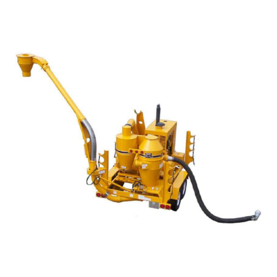
4 OPERATION TO THE NEW OPERATOR OR OWNER The Walinga Ultra-Vac® is specifically Many features incorporated into this machine designed to vacuum up grain and move it in a are the result of suggestions made by stream of pressurized air. A high capacity air customers like you. -
Page 24: Machine Components
MACHINE COMPONENTS The air pump or blower is the key component in the On the discharge side of the blower, the Ultra-Vac® and is driven by the diesel engine pressurized air flows through the airlock where it through a belt drive system. The blower moves air picks up a metered quantity of grain and moves it through the machine. -
Page 25: Break-In
Although there are no operational restrictions on the Ultra-Vac® when used for the first time, it is recommended that the following mechanical items Efficient and safe operation of the Walinga Ultra- be checked: Vac® requires that each operator reads and understands the operating procedures and all A. -
Page 26: Controls
CONTROLS All controls on the Ultra-Vac® are located on the rear of the machine. Review this section carefully to familiarize yourself with the function and movement of each control before starting. 1. Airlock Control: The right valve controls the operation of the airlock. -
Page 27: Attaching/Unhooking
4.6 ATTACHING/UNHOOKING The Ultra-Vac® should always be parked on a level, dry area that is free of debris and foreign objects. Follow this procedure when attaching. 1. Clear the area of bystanders and remove foreign objects from the machine and working area. -
Page 28: Machine Preparation
4.7 MACHINE PREPARATION Before the Ultra-Vac® can be used it must be set up and prepared for operation. When setting-up, follow this procedure: 1. Clear the area of bystanders, especially small children. 2. Be sure you select a spot that has sufficient space to locate the machine and enough clearance to allow trucks to drive under the discharge cyclone. -
Page 29: Operating
4.8 OPERATING When operating the Ultra-Vac®, follow this procedure: 1. Clear the area of bystanders, especially small children, before starting. 2. Review and follow the Pre-Operation Checklist (See Section 4.4). 3. Be sure the machine is correctly positioned and set-up per Section 4.7. The trucks should Fig. - Page 30 OPERATING (cont'd) Airlock Speed vs Grain (rpm) 5614D 6614D 7614D 8614D 5. Starting Machine (cont’d) Slowly engage the PTO/Clutch control to Grain the drive system. (Fig. 4-8 ) Barley 50-70 55-70 65-70 Increase engine speed until it is at 3/4 throttle. Wheat g.
- Page 31 7. Maximum Capacity: a. The nozzle should be placed into the grain with the inlet below the surface of the grain but not below the airslide. It is recommended that some air be allowed to enter with the grain to obtain the best capacity.
- Page 32 OPERATING (cont'd) 10. Stopping Machine Cont’d: Disengage hydraulic circuit and slowly disengage PTO clutch. Stop engine by turning ignition key to OFF and REMOVE. 11. Pre-Cleaner: The machine is designed with a cleaner between the blower and the receiver tank to remove dust and dirt from the air stream.
-
Page 33: Transporting
OPERATING (cont'd) i. If the airlock becomes jammed, use the hydraulics to reverse the direction of airlock rotation and clear the obstruction. j. When on top of grain, do not push the nozzle into the pile next to the feet. The suction will pull the nozzle and the operator into the pile. - Page 34 TRANSPORTING Walinga Ultra-Vacs® are designed to be easily and conveniently moved from location to location. When transporting, follow this procedure: 1. Be sure all bystanders are clear of the machine. 2. Be sure that the Ultra-Vac® is hitched positively to the towing vehicle. Always use a retainer in the drawbar pin and a safety chain between the machine and the towing vehicle.
-
Page 35: Storage
TRANSPORTING (cont’d) 5. Lower cyclone, and swing around into the At the end of the season, the machine should be boom saddle. thoroughly inspected and prepared for storage. Repair or replace any worn or damaged 6. Do not allow riders on the machine or towing components to prevent any unnecessary down vehicle. -
Page 36: Service And Maintenance
Use an SAE multi-purpose high temperature grease with extreme pressure (EP) characteristics. Also acceptable is an SAE multi-purpose lithium based grease. 2. Blower Oil: Use Walinga Blower oil (part# 98-13813-6) Imperial 80W 140 GX Extra gear oil or equivalent. Reservoir Capacity: +1 1/4 quarts MODEL... - Page 37 5.1.3 SERVICING INTERVALS 8 Hours or Daily 1. Check the tension and alignment of the input drive belts. (fig. 5-3) See Maintenance Section. 2. Check the oil level in the blower reservoirs (2 locations). Fig. 5-1 Blower End Views Fig. 5-2 Gear End 40 Hours 1.
- Page 38 5.1.3 SERVICING INTERVALS (cont’d) 20 Hours 1. Check the condition of the wear liner in the discharge cyclone.(fig. 5-4) Replace as required. Fig. 5-4 Discharge Cyclone & Boom Cylinder 40 Hours 1. Lubricate the exposed rod end of the boom lift cylinder (fig.
- Page 39 5.1.3 SERVICING INTERVALS (cont’d) 100 Hours or Annually 1. Change the oil in the blower reservoirs (2 reservoirs). Fig. 5-6 Blower Reservoirs Fig 5-7 Vacuum Relief Valve 2. Check the function of the vacuum and pressure relief valves. Fig 5-8 Pressure Relief Valve 3.
- Page 40 5.1.4 SERVICE RECORD See Lubrication and Maintenance sections for details of service. Copy this page to continue record. HOUR READING AT TIME OF SERVICE: SERVICED BY: Every 8 Hours or Daily Check Tension and Align Input Drive Belts Check oil level in Blower Reservoirs (2) Clean Blower Breathers Every 20 Hours...
-
Page 41: Maintenance
Follow this procedure when checking and 5.2 MAINTENANCE adjusting belt tension and pulley alignment. By following a careful service and maintenance 1. Clear the area of bystanders, especially small program for your machine, you will enjoy many children. years of trouble-free service. Place all controls in neutral, stop the engine, 5.2.1 BELT TENSION AND... -
Page 42: Belt Tension And Alignment
5.2.1 BELT TENSION AND ALIGNMENT (cont'd) 4. Use a 10 pound weight to determine the belt deflection in a static condition. Adjusting Tension: a. Loosen the jam nuts on the adjusting Fig. 5-10 Deflection bolts. Loosen bearing bolts slightly. b. Turn the adjusting bolt to set the tension. Turn both bolts the same amount to maintain pulley alignment. - Page 43 6. Pulley Alignment: a. Lay a straight-edge across the faces of the Use the bearing housing assembly anchor two pulleys. bolts to align the blower pulley. Tighten anchor bolts to their specified torque. b. If the gap between the pulley and the Set the belt tension.
- Page 44 5.2.2 BLOWER OIL CHANGING AND BREATHER CLEANING The gears that drive and time the blower lobes run in an oil bath for lubrication. Maintaining the correct level in the reservoirs and changing every 100 hours will insure proper lubrication. When maintaining the blower, follow this procedure: 1.
-
Page 45: Blower Oil Changing And Breather Cleaning
5.2.2 BLOWER OIL CHANGING AND BREATHER CLEANING (cont'd) 5. Changing Oil: a. Place a collection pan or pail under each drain plug. b. Remove each drain plug. c. Flush each case and allow several minutes to drain. d. Dispose of the oil in an approved manner. Do not contaminate the worksite with used oil. -
Page 46: Airlock
5.2.3 AIRLOCK The airlock acts as a seal between the vacuum and pressure sides of the machine and is located at the bottom of the receiver tank. As the rotor turns, a pocket is filled with material when it points upward. - Page 47 e. File the ends of each replacement blade 5.2.3 AIRLOCK (cont'd) so there is approximately 0.006 inches of 3. Checking Tip Clearance: clearance between the ends and the a. Checking the airlock can be done through housing. the inspection door. Mount the blades to their respective vane b.
-
Page 48: Air System Relief Valves
5.2.4 AIR SYSTEM RELIEF VALVES The air in this system is moved by the blower. It draws air into the intake side and creates a vacuum that can pick up and draw material into the system. As the air moves through the blower, it becomes pressurized and flows through the airlock to move material out of the system and to its destination. -
Page 49: Trouble Shooting
TROUBLE SHOOTING The Walinga Ultra-Vac® is a high capacity air pump that creates a vacuum for picking up grain and supplies pressurized air for moving the grain. It is a simple and reliable system that requires minimum maintenance. In the following section, we have listed many of the problems, causes and solutions to the problems that you may encounter. - Page 50 PROBLEM CAUSE SOLUTION Slow discharge of grain (cont'd). Defective blower. Check clearance between lobes and case. Excessive clearance will decrease air flow. Consult your dealer. Defective airlock. Check that tip clearance is 0.004 inches. Adjust or replace tips as required. Improper setting of flow control Reset flow control.
- Page 51 PROBLEM CAUSE SOLUTION Hydraulics overheating (cont’d) Poor oil quality. Replace with oil of required specifications. Defective hose or tube. Check hoses, lines and couplers. Repair or replace as required. Improper circuit. Check for proper system setting. i.e. open or close. Wrong airlock speed.
-
Page 52: Blower
BLOWER PROBLEM CAUSE SOLUTION Low air volume. Slow speed. Check blower speed with tach. Increase speed. Check for slipping belts. Adjust belt tension as required. Piping blocked. Check inlet and outlet piping. Remove obstruction. Check relief valves. Clean, repair or replace as required. Excessive pressure rise. -
Page 53: V-Belt Drive
V-BELT DRIVE PROBLEM CAUSE SOLUTION Loss in drive speed. Belts slipping. Tighten belts as required. Localized belt wear. Check cross-section dimension. a. If narrow, pulley spinning. b. If swollen, belt failing internally. Unequal stretch on belts. Defective belts. Replace with matched set. -
Page 54: Specifications
SPECIFICATIONS 7.1 MECHANICAL MODEL CORN & DISCHARGE CAPACITY* WHEAT BEANS LINE SIZE BARLEY HEIGHT Bu/Hr (tones/hr) 4510D 1200 1000 4 in (100mm) 13ft-4in min (30) (27) (24) (4.06m) 5614D 2500 2200 1900 5 in (125mm) 14 ft min (64) (58) (51) (4.26m) 6614D... -
Page 55: Bolt Torque
7.2 BOLT TORQUE CHECKING BOLT TORQUE The tables shown below give correct torque values for various bolts and capscrews. Tighten all bolts to the torques specified in chart unless otherwise noted. Check tightness of bolts periodically, using bolt torque chart as a guide. Replace hardware with the same strength bolt. ENGLISH TORQUE SPECIFICATIONS Bolt Bolt Torque... - Page 57 CORPORATE HEAD OFFICE: 5656 Highway 6N RR#5, Guelph, Ontario,N1H 6J2 PHONE: (888) 925-4642 FAX: (519) 824-5651 www.walinga.com AGRI-VAC MANUFACTURING FACILITY: 938 Glengarry Cres., Fergus, Ontario Canada N1M 2W7 Tel: (519) 787-8227 Fax: (519) 787-8210 DISTRIBUTION AND SERVICE CENTRES: 5656 Highway 6N, Guelph, Ontario Canada,N1H 6J2 Tel: (888) 925-4642 FAX: (519) 824-5651 1190 Electric Ave.
Need help?
Do you have a question about the ULTRA-VAC 5614D and is the answer not in the manual?
Questions and answers