
Related Manuals for Walinga AGRI-VAC 5614


Summary of Contents for Walinga AGRI-VAC 5614
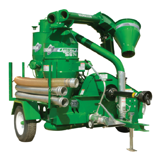
- Page 1 6614 5614 7614 7816 AGRI-VAC Model 5614 to 7816 OPERATOR'S MANUAL and PARTS BOOK TOUGH TO BEAT IN THE LONG RUN...
- Page 3 WALINGA Start-up/Commissioning Form This form must be filled out by the sales representative and/or dealer; and signed by both the sales representative and/or dealer and the customer at the time of delivery. Delivery date: MM/DD/YYYY Owner Operator Name Sales Representative / Dealer Name...
- Page 4 Standards Institute). Please note: It is a requirement in NFPA 652 that the final operator completes a dust hazard analysis (DHA) of their facility and the products and processes it contains. Based on this, Walinga understands that a DHA is required to be completed by the owner/operator prior to start-up/commissioning. In the event that a DHA is not available at start-up/commissioning, the owner/operator must provide written acknowledgement of their responsibility and intention to complete a DHA.
-
Page 5: Warranty Registration Form & Inspection Report
Warranty Period The warranty period for the Walinga Warranty shall expire on the date that is the earlier of: two (2) years after the date of delivery to the original customer; or upon the expiration of five hundred (500) hours of operation; whichever date comes first. -
Page 6: Agri-Vac Warranty
The Walinga Warranty and all questions regarding its enforceability and interpretation are governed by the law of the country, state or province in which you purchased your Walinga equipment. The laws of some jurisdictions limit or do not allow the disclaimer of consequential damages. - Page 7 Dear Customer, Thank you for choosing WALINGA PNEUMATIC CONVEYING SYSTEMS. For your convenience, should you require any information related to Parts, Service or Technical Engineering, please contact one of the following Walinga Personnel in Guelph at 1-888 925-4642 unless noted*...
-
Page 8: Serial Number Location
SERIAL NUMBER LOCATION Always give your dealer the Serial Number of The Serial Number plates are located where your Walinga unit when ordering parts or indicated. Please mark the number in the requesting service or other information. space provided for easy reference. -
Page 9: Table Of Contents
TABLE OF CONTENTS ..............3 Warranty Registration Form & Inspection Report AGRI-VAC WARRANTY................4 SERIAL NUMBER LOCATION ..............6 INTRODUCTION ................11 SAFETY ................... 12 GENERAL SAFETY .......................13 OPERATING SAFETY ....................14 SAFETY AROUND BINS,SILOS,TANKS AND BOOT PITS………. ……………. 15 MAINTENANCE SAFETY ....................15 HYDRAULIC SAFETY....................16 STORAGE SAFETY.......................16 TRANSPORT SAFETY ....................17... - Page 10 Table of Contents (con't) SERVICE AND MAINTENANCE............46 SERVICE ........................46 5.1.1 FLUIDS AND LUBRICANTS ..................46 GREASING ........................46 5.1.2 5.1.3 SERVICING INTERVALS ..................... 47 5.1.4 SERVICE RECORD ..................... .53 BELT TENSION AND ALIGNMENT ................54 5.2.1 5.2.2 BLOWER OIL CHANGING AND BREATHER CLEANING ..........58 5.2.3 AIRLOCK ........................
- Page 11 LIST OF FIGURES SECTION 3 SAFETY DECALS Fig. 3-1 Typical Decals (Front Driverside) ................19 Fig. 3-2 Typical Decals Rear Side Of Belt Cover............... 19 Fig. 3-3 Typical Decals For Hydraulic Boom Rotation .............. 21 Fig. 3-4 Typical Decals On Receiver Tank ................21 Fig.
- Page 12 LIST OF FIGURES (Cont’d) SECTION 5 SERVICE AND MAINTENANCE Fig. 5-1 PTO Shaft Lubrication Points..................Fig. 5-2 Drive Belts........................Fig. 5-3 Blower Reservoir Schematics..................Fig. 5-4 Blower Reservoirs (Front)..................… Fig. 5-5 Blower Reservoirs (Rear) ................... .. Fig. 5-6 Check the Wearliner in Discharge Cyclone..............
-
Page 13: Introduction
Keep this manual handy for frequent reference and to pass on to new operators or owners. Call your Walinga dealer if you need assistance, information or additional copies of the manual. Contact your dealer for a complete listing of parts. -
Page 14: Safety
SAFETY ALERT SYMBOL This Safety Alert The Safety Alert symbol identifies symbol means important safety messages on the Walinga Agri-Vac and in the ATTENTION! manual. When you see this BECOME ALERT! symbol, be alert to the possibility YOUR SAFETY IS of personal injury or death. -
Page 15: General Safety
ALL Safety and Operating instructions in the manual and to follow these. All accidents can be avoided. • Walinga feels that a person who has not read, understood and been trained to follow all operating and safety instructions is not qualified to operate the equipment. An untrained operator exposes himself and bystanders to possible serious injury or death. -
Page 16: Operating Safety
7. Place all controls in neutral, stop the engine or disconnect all electrical power sources, set the park brake on tractor or towing vehicle, remove the ignition key and wait for all moving parts to stop before servicing, adjusting, repairing or unplugging. 8. -
Page 17: Safety Around Bins,Silos,Tanks And Boot Pits
2.3 SAFETY AROUND BINS,SILOS, TANKS AND BOOT PITS Working in and around bins, silos, and tanks and boot pits. Agri-Vac operators and all other personnel assisting should strictly adhere to the procedures outlined below before entering a storage structure. For additional details regarding these procedures, reference OSHA Standards, or your local regulations. -
Page 18: Maintenance Safety
MAINTENANCE SAFETY 1. Follow ALL the operating, maintenance and safety information in the manual. 2. Support the machine with blocks or safety stands when changing tires or working beneath. 3. Follow good shop practices: - Keep service area clean and dry. - Be sure electrical outlets and tools are properly grounded. -
Page 19: Transport Safety
TRANSPORT SAFETY Refer to Section 4.11 TRANSPORTING - Towing (page 43) for detailed information and regulations. 1. Make sure you are in compliance with all local regulations regarding transporting equipment on public roads and highways. 2. Make sure that all the lights and reflectors that are required by local highway and transport authorities are in place, are clean and can be seen clearly by all overtaking and oncoming traffic. -
Page 20: Sign-Off Form
2.10 SIGN-OFF FORM Walinga Inc. follows the general Safety Standards specified by the American Society of Agricultural Engineers (ASAE) and the Occupational Safety and Health Administration (OSHA). Anyone who will be operating and/or maintaining the Agri-Vac must read and clearly understand ALL Safety, Operating and Maintenance information presented in this manual. -
Page 21: Safety Decal Locations
3 SAFETY DECAL LOCATIONS The types and locations of some of the safety decals on the equipment, are shown on the next pages. Good safety requires that you familiarize yourself with the various safety decals, the type of warning and the area, or particular function related to that area, that requires your SAFETY AWARENESS. •... - Page 22 3 SAFETY DECAL LOCATIONS (CONT’D) **On 540 rpm models use decal 53-15652-6 A ** Agri-Vac Operator’s Manual 34-18148-6...
-
Page 23: Fig. 3-3 Typical Decals For Hydraulic Boom Rotation
3 SAFETY DECAL LOCATIONS Fig. 3-3 Typical Decals For Hydraulic Boom Fig. 3-4 Typical Decals On Receiver Tank Rotation (Optional ) Agri-Vac Operator’s Manual 34-18148-6... -
Page 24: Fig. 3-5 Intake Nozzle Decal (Typical)
3 SAFETY DECAL LOCATIONS (CONT’D) Fig. 3-5 Intake Nozzle Decal (Typical). Fig. 3-6 Decal (With Belt Cover Removed.) The types and locations of some of the safety decals on the equipment are shown on the preceding pages. Good safety requires that you familiarize yourself with the safety decals, the type of warning and the area, or particular function related to that area, which requires your SAFETY AWARENESS. -
Page 25: Operation
4 OPERATION 4.1(a) OPERATION (FOR UNITS WITH ELECTRIC MOTORS) 4.1.1. Safety: a. Disconnect all electrical power before servicing, adjusting, or lubricating equipment. Install lock-out if necessary. b. All electrical hook-ups should be in accordance to the National Electrical Code (NEC), and all local regulations. -
Page 26: B) Operation ( Tractor Pto Units)
4.1(b) OPERATION ( TRACTOR PTO UNITS) TO THE NEW OPERATOR OR OWNER The Walinga Agri-Vac is specifically Many features incorporated into this machine are the designed to vacuum up grains, and move it in result of suggestions made by customers like you. -
Page 27: Machine Components
MACHINE COMPONENTS* The air pumps or blowers are the key components in the Agri-Vac and are driven by the the tractor PTO / electrical power source (fig 4-3), through a belt drive system. The blower moves air through the machine. On the intake side, the blower creates a vacuum in the receiver tank and intake lines for picking up grain. -
Page 28: Break-In
Then go to normal servicing and maintenance schedule defined in the Maintenance Section. PRE-OPERATION CHECKLIST Efficient and safe operation of the Walinga Agri-Vac® requires that each operator reads and understands the operating procedures and all related safety precautions outlined in this section. A pre-operation checklist is provided for the operator. -
Page 29: Equipment Matching
11. Check that the PTO driveline is pinned to the tractor shaft and the guard is chained to the frame. 12. Close and secure all guards. 4. 6 EQUIPMENT MATCHING The Walinga Agri-Vac® is designed to be used with Agricultural tractors/power units. To insure a good performance, the following list of specifications must be met: 1. Horsepower: (Table 1) Use Table 1 as a guide in determining the minimum recommended horsepower for different models. -
Page 30: Controls
4.7 CONTROLS All controls on the Agri-Vac® are located on the rear of the machine. Review this section carefully to familiarize yourself with the function and movement of each control before starting. Boom Lift (Control #2 fig 4-5): This valve controls the boom position. Pull on the lever to raise the boom and push to lower. Place in the centre position for no boom movement. - Page 31 Airlock Control (Control #4 fig 4-5) : The right valve controls the operation of the airlock. Pull on the control to operate the IMPORTANT airlock in the forward direction and push to operate in the reverse direction. Stop the Do not attempt to raise boom airlock by placing the lever in the centre while airlock is in operation.
-
Page 32: Attaching/Unhooking
ATTACHING/UNHOOKING The Agri-Vac® should always be parked on a level, dry area that is free of debris and foreign objects. Follow this procedure when attaching: 1. Clear the area of bystanders and remove foreign objects from the machine and working area. 2. -
Page 33: Fig. 4-9 Pto Shaft Connected
8. Connect the PTO shaft: a. Check that the PTO driveline telescopes easily and that the shield rotates freely. b. Attach the driveline to the tractor/power unit by retracting the locking pin or pulling back on the lock collar. Slide the yoke over the shaft and push on the yoke until the lock pin or lock collar clicks into position. -
Page 34: Fig. 4-11 Position Of Machine To Bin 12Ft (4 M)
4.9 Machine Preparation Before the Agri-Vac® can be used it must be set up and prepared for operation. When setting-up, follow this procedure: Clear the area of bystanders, especially small children. Be sure you select a spot that has sufficient space to locate the machine and enough clearance to allow trucks to drive under the discharge cyclone. -
Page 35: Machine Preparation
MACHINE PREPARATION Release split boom security latch and lift boom extension out of the saddle. Fig. 4-13 Security Latch & Boom Saddle. Swing boom extension around 180 deg until air line is straight. Secure boom extension by clamping the latch eye over hook. Adjust clamp if it is necessary to prevent air leakage at joint. -
Page 36: Fig. 4-16 Positioning
14. Use the arm next to the boom pivot to swing the discharge boom around or use the hydraulic boom rotation(HBR) if so equipped. Fig. 4-16 Positioning 15. Swing the boom into a working position that will allow a truck to drive under the discharge cyclone. -
Page 37: Operating
4.10 OPERATING When operating the Agri-Vac®, follow this procedure: Clear the area of bystanders, especially small children, before starting. Be sure the machine is attached to the tractor/power unit as per Sect.4.8. Review and follow the Pre-Operation Checklist (Section 4.5). Be sure the machine is correctly positioned and set-up per Section 4.9. -
Page 38: Starting Machine With A Tractor
4.10.7A. Starting Machine With a Tractor (cont’d) c. Check that the machine hydraulics are matched to the tractor hydraulics. i. Switch the machine to closed centre hydraulics if the tractor is so equipped. ii. Machines without a dual system are plumbed for open centre hydraulics. -
Page 39: Starting Machine With An Electric Motor
4.10 OPERATING 4.10.7 STARTING MACHINE (cont’d) 7B. Starting Machine with an Electric Motor Check the condition of the electrical cord and the plug to ensure that they are in good condition. DO NOT OPERATE IF DAMAGED! a. Start the motor. b. -
Page 40: Fig. 4-21 Airlock Speed Flow Divider And Direction Wheel
4.10 OPERATING (cont'd) 8. Airlock Speed: Table 2 Airlock Speed vs. Grain MODEL Refer to the following table as a guide for 7614 7614HD 5614 setting the airlock speed. Use the flow With 1618 With 2018 7816 6614 control to adjust the speed and count the PRODUCT revolutions using the arrow on the wheel. -
Page 41: Fig. 4-22 Product In The Window
4.10 OPERATING 9. Maximum Capacity (cont'd): c. Watch the amount of grain on the window in the receiver tank. Keep the window full yet keep the product moving. There are several ways to control the amount of grain on the window: i. -
Page 42: Fig. 4-24 Using The Clean-Up Nozzle In The Bin
4.10 OPERATION (cont’d) b. Storage: To prepare the machine for storage, remove the inlet pipe and spray the blower clean with water, then run at idle for 5 minutes to dry the inside of the tank, piping, blower and airlock. This will prevent any residue from caking on the internal components. -
Page 43: Fig. 4-26 Emptying The Pre-Cleaner
4.10 OPERATION 14. Pre-Cleaner: The machine is designed with a cleaner between the blower and the receiver tank to remove dust and dirt from the air stream. Empty the pre-cleaner every 1700 bushels (45 Tonnes) during normal operating conditions. Clean or empty pre-cleaner canister more frequently in dirty or dusty conditions. -
Page 44: Fig. 4-28 Seconds To Suffocation
4.10 OPERATION (cont'd) 16. Entering Bins,Silos,Tanks and Boot Pits: (see also Section 2.3) Note: Do not enter the bin or the silo when grain is stuck on the walls. Avalanching a. Make sure the bin is properly vented. grain can cause suffocation! b. -
Page 45: Transporting
4.11 TRANSPORTING (Towing) Use ANSI/ASAE S279.17 July 2013 as a Walinga Agri-Vacs® are designed to be easily minimum standard for Lighting and and conveniently moved from location to Marking of Agricultural Equipment on location. Highways whether towing the Agri-Vac during daytime or nighttime. -
Page 46: Fig. 4-29 Security Latch Engaged On Boom Extension
4.11 TRANSPORTING -Towing (cont’d) Table 3 Road Speed vs Weight Ratio 8. **Make sure the SMV (Slow Moving Vehicle) emblem and all the lights and reflectors that Weight of fully equipped are required by the local highway and or loaded Agri-Vac(s) transport authorities are in place, are clean Road Speed relative to the weight of... -
Page 47: Storage
4.12 STORAGE 6. Install the plugs into the receiver tank inlet. 7. Empty the pre-cleaner tank. Check inside the receiver tank to make sure it is empty. 8. Apply "never seize" or grease to the PTO input shaft and the boom cylinder ram. At the end of the season, the machine 9. -
Page 48: Service And Maintenance
1. Grease: Use an SAE multi-purpose high temperature grease with extreme pressure (EP) characteristics. Also acceptable is an SAE multi-purpose lithium based grease. 2. Blower Oil: Use Walinga Blower oil (part# 98-13813-6) Table 4 MODEL 5614/6614 7816 & 7614 LOCATION... -
Page 49: Servicing Intervals
5.1.3 SERVICING INTERVALS Every 8 Hours or Daily 1. Lubricate the PTO shaft (4 locations). Error! No table of figures entries found. Fig. 5-1 PTO Shaft Lubrication Points. 2. Check the tension and alignment of the input drive belts. See Maintenance Section 5.2.1 Fig. -
Page 50: Fig. 5-3 Blower Reservoir Schematics
5.1.3 SERVICING INTERVALS (cont’d) Every 8 Hours or Daily (cont’d) 3. Check the oil level in the blower reservoirs (2 locations). 4. Clean blower breathers Fig. 5-3 Blower Reservoir Schematics. Fig. 5-4 Blower Reservoirs (Front) Fig. 5-5 Blower Reservoirs (Rear) Agri-Vac Operator’s Manual 34-18148-6... -
Page 51: Fig. 5-6 Check The Wearliner In Discharge Cyclone
5.1.3 SERVICING INTERVALS Every 20 Hours 1. Lubricate the PTO shaft (1 location – see Fig. 5-1). 2. Check the condition of the wear liner in the discharge cyclone. Replace as required. 3. Lubricate the blower drive shaft. 4. Check the airlock wiper blades Fig. -
Page 52: Fig. 5-9 Splined Shaft
5.1.3 SERVICING INTERVALS (cont’d) Every 40 Hours (cont’d) 3. Lubricate the splined input shaft and bearings (2 locations). Fig. 5-9 Splined Shaft. 4. Lubricate the outboard bearing (2 locations) Fig. 5-10 Outboard Bearing. Agri-Vac Operator’s Manual 34-18148-6... -
Page 53: Fig. 5-11 Blower Reservoirs
5.1.3 SERVICING INTERVALS Every 100 Hours or Annually 1. Change the oil in the blower reservoirs (2 locations) Fig. 5-11 Blower Reservoirs. 2. Check the function of the vacuum and pressure relief valves. Check the airlock tip blade clearances. If clearances are over .010 adjust the blades Fig. -
Page 54: Fig. 5-14 Cyclone Line Seal
5.1.3 SERVICING INTERVALS Every 100 Hours or Annually (cont’d) 3. Check the condition of the air line seals. Fig. 5-14 Cyclone Line Seal. Fig. 5-15 Flex Hose Seals. Agri-Vac Operator’s Manual 34-18148-6... -
Page 55: Service Record
5.1.4 SERVICE RECORD See Lubrication and Maintenance sections for details of service. Copy this page to continue record. HOUR READING AT TIME OF SERVICE: SERVICED BY: Every 8 Hours or Daily Lubricate PTO Shaft (4) Check Tension and Align Input Drive Belts Check oil level in Blower Reservoirs (2) Clean Blower Breathers... -
Page 56: Belt Tension And Alignment
5.2 MAINTENANCE By following a careful service and maintenance program for your machine, you will enjoy many years of trouble-free service. 5.2.1 BELT TENSION AND ALIGNMENT Rotational power from the engine is transmitted to the blower through the belt drive. To obtain efficient transmission of power and good belt life, ensure the belts are properly tensioned and the pulleys are aligned. -
Page 57: Fig. 5-17 Belt Deflection
5.2.1 BELT TENSION AND ALIGNMENT 5. Use a 10 pound weight to determine the belt deflection in a static condition. Fig. 5-16 Belt Deflection Fig. 5-17 Belt Deflection. 6. Adjusting Tension: a. Loosen the jam nuts on the adjusting bolts. Loosen bearing bolts slightly. b. -
Page 58: Fig. 5-19 Pulleys
7. Pulley Alignment: a. Lay a straight-edge across the faces of the two pulleys. b. If the gap between the pulley and the straight-edge exceeds 1/16 in (1.5 mm), the pulleys must be realigned. c. Review the types of alignment before starting. -
Page 59: Fig. 5-21 Adjusting Bolts At Input Shaft
5.2.1 BELT TENSION AND ALIGNMENT (cont’d) 7. Pulley Alignment (cont'd): d. Use the adjusting bolts on the input shaft to align the input pulley. Tighten jam nuts when alignment has been completed. Fig. 5-21 Adjusting Bolts At Input Shaft. e. Use the bearing housing assembly anchor bolts to align the blower pulley. -
Page 60: Blower Oil Changing And Breather Cleaning
5.2.2 BLOWER OIL CHANGING AND BREATHER CLEANING The gears that drive and time the blower lobes run in an oil bath for lubrication. Maintaining the correct level in the reservoirs and changing every 100 hours will insure proper lubrication. When maintaining the blower, follow this procedure: 1. -
Page 61: Fig. 5-26 Blower Schematics
Install and tighten the drain plugs. f. Remove the fill and level plugs. g. Add Walinga Blower oil or equivalent to each reservoir until the oil is just starting to come out of the level plug hole. -
Page 62: Airlock
5.2 MAINTENANCE (cont’d) 5.2.3 AIRLOCK The airlock acts as a seal between the vacuum and pressure sides of the machine and is located at the bottom of the receiver tank. As the rotor turns, a pocket is filled with material when the rotor points upward. As the pocket rotates, material is moved to the bottom and is moved into the pressure side of the system. - Page 63 5.2.3 AIRLOCK h. Rotate the airlock and listen if the blades touch the housing anywhere. A slight touch is alright. Hint: Number blades when done. i. Repeat mounting procedure with the other blades. 4. Wiper Blade j. Turn the rotor all the way around after A wiper blade is located at the top of the each blade is installed to be sure no airlock to clean the tips as the airlock turns.
-
Page 64: Shear Pin
Be careful not to enlarge the holes. 4. Shear bolts can be replaced with a standard shear bolt with UNC thread. Check with Walinga’s Engineering Department for the Fig. 5-31 Shear Pin. proper size for your year and model. -
Page 65: Air System Relief Valves
5.2.5 AIR SYSTEM RELIEF VALVES The air in this system is moved by the blower. It draws air into the intake side and creates a vacuum that can pick up and draw the material into the system. As the air moves through the blower, it becomes pressurized and flows through the airlock to move the material out of the system and to its destination. -
Page 66: Trouble Shooting
6 TROUBLE SHOOTING The Walinga Agri-Vac® is a high capacity air pump that creates a vacuum for picking up grain and supplies pressurized air for moving the grain. It is a simple and reliable system that requires minimum maintenance. In the following section, we have listed many of the problems, causes and solutions to the problems that you may encounter. - Page 67 6.1 MOBILE TRANSFER UNIT (Cont’d) PROBLEM CAUSE SOLUTION Power source Check tractor or motor RPM Slow discharge of grain. Air leaks Tighten all pressure connections. Be sure seals are in good condition. Check pressure relief valve. Clean or replace as required. Defective blower.
-
Page 68: Pto Shaft
Some oil seeds create buildup inside the blower as well as the muffler. Wash and rinse with water. Replace shear pin with genuine Walinga parts. For pin size contact the Walinga Engineering Dept. a. 2 shear pins b. 1 shear pin PTO engaged too quickly. -
Page 69: Airlock
6.3 AIRLOCK PROBLEM CAUSE SOLUTION Noisy airlock. Tips hitting case. Readjust tips where applicable. Airlock stalls. Airlock jammed. Reverse airlock direction to clear. Disconnect hydraulic hoses. Remove obstruction from airlock by opening inspection door or discharge elbow. Insufficient oil flow. Check couplings or lines. -
Page 70: Blower
6.4 BLOWER PROBLEM CAUSE SOLUTION Low air volume. Slow speed. Check blower speed with tachometer. Increase speed. Check for slipping belts. Adjust the belt tension as required. Piping blocked. Check inlet and outlet piping. Remove obstruction. Check relief valves. Clean, repair or replace as required. -
Page 71: V-Belt Drive
6.5 V-BELT DRIVE PROBLEM CAUSE SOLUTION Loss in drive speed. Belts slipping. Tighten belts as required. Localized belt wear. Check cross-section dimension. a. If narrow - pulley spinning. b. If swollen - belt failing internally. Unequal stretch on belts. Defective belts. Replace with matched set. -
Page 72: Mechanical Specifications
7. MECHANICAL SPECIFICATIONS* 7.1 MECHANICAL Table 6 Mechanical Specifications Capacity* Bu/Hr (Tonnes/Hr) Line Discharge Model PTO Speed Size Height Corn & Wheat Beans Barley 5614 70-85 2500 (30) 2200 (58) 1900 (51) 5 in 6614 6 in 110-130 3600 (92) 3200-(84) 2800 (75) 4500... -
Page 73: Bolt Torque
BOLT TORQUE CHECKING BOLT TORQUE The tables shown below give correct torque values for various bolts and cap screws. Tighten all bolts to the torques specified on chart unless otherwise noted. Check tightness of bolts periodically, using bolt torque chart as a guide. Replace hardware with the same strength bolt. Table 7 Imperial Torque Specifications Bolt Torque * Bolt... - Page 74 NOTES: Agri-Vac Operator’s Manual 34-18148-6...
-
Page 75: Agri-Vac Parts List Addendum
8 AGRI-VAC PARTS LIST ADDENDUM This section contains a Parts List and Exploded views for the following Agri-Vac models: 5614 DLX,HBR,SCH,FRL …………..74,75 6614 DLX,HBR,SCH,FRL ..…………76,77 *7614HD DLX,HBR,SCH,FRL … ..……...78,79 5614 Deluxe(DLX) with 1000 RPM PTO, with optional Self Contained Hydraulics (SCH) Full Rhino Liner (FRL), Hydraulic Boom Rotation (HBR), Dual Inlets(DI) and a Precleaner. -
Page 76: 5614 Dlx, Hbr, Frl, Sch & Di Parts List
5614 DLX, HBR, FRL, SCH & DI PARTS LIST (see fig 8-1) ITEM PART NO. DESCRIPTION ITEM PART NO. DESCRIPTION 11-03615-6 Sheave, 18.4 X 5-B X SF 11-78509-5 Receiver Installation,5614 DI FRL W/PC,2011 11-03617-6 Bushing SF X 1.75" X .375" KW 11-78512-5 Split Boom, Female End-5"-FRL -2011 11-03632-6... -
Page 77: Fig. 8-1 Exploded View 5614 Dlx, Hbr, Frl, Sch & Di
Fig. 8-1 Exploded View 5614 DLX, HBR, FRL, SCH & DI Agri-Vac Operator’s Manual 34-18148-6... -
Page 78: 6614 Dlx, Hbr , Frl, Sch & Di Parts List
6614 DLX, HBR , FRL, SCH & DI PARTS LIST (see fig 8-2) ITEM PART NO. DESCRIPTION ITEM PART NO. DESCRIPTION Blower, 614,2.25" Flat Ring 7.370” x 6.125” x .25” Rubber 50-69733-5 96-13067-6 Gasket, Blower Mount, 614 DP6 Plug With Chain 96-09117-6 38-07796-5 614 -6”... -
Page 79: Fig. 8-2 Exploded View 6614 Dlx, Hbr, Frl, Sch & Di
Fig. 8-2 Exploded View 6614 DLX, HBR, FRL, SCH & DI Agri-Vac Operator’s Manual 34-18148-6... -
Page 80: 7614Hd Dlx, Hbr , Frl , Sch & Di Parts List
7614HD DLX, HBR , FRL , SCH & DI PARTS LIST (see fig 8-3) ITEM PART NO. DESCRIPTION ITEM PART NO. DESCRIPTION 50-69733-5 Blower,614,2.25" 96-17109-6 Flat Ring 8.370”x 7.125” x .250” Rubber 96-09117-6 Gasket, Blower Mount, 614 11-88803-4 Liner, Frustum ,Full, Receiver, 7614,HD, 2011 38-29560-4 614 - 6”... -
Page 81: Fig. 8-3 Exploded View 7614Hd Dlx, Hbr, Frl, Sch & Di
Fig. 8-3 Exploded View 7614HD DLX, HBR, FRL, SCH & DI Agri-Vac Operator’s Manual 34-18148-6... - Page 82 NOTES:...
-
Page 83: Fig. 8-4 Birds-Eye View 2016 Models
5614/6614/7614 & 7816 DLX (2016) DELUXE, HYDRAULIC BOOM ROTATION,FULL RHINO LINER, & DUAL INLET 7614 DLX 7816 DLX 5614 DLX / 6614 DLX HBR, FRL, SCH, & DI 2016 HBR, FRL, SCH, & DI 2016 HBR, FRL, SCH, & DI 2016 Fig. -
Page 84: 5614 Dlx(2016) Hbr, Frl, Sch & Di Parts List
5614 DLX HBR FRL 2016 PARTS LIST (see fig. 8-5) ITEM NUMBER DESCRIPTION ITEM NUMBER DESCRIPTION 11-03615-6 Sheave, 18.4 X 5-B X SF 11-94961-4 Boom Flex Hose Sup,5614,2014 11-03617-6 Bushing, SFX 1-3/4" X 3/8"KW 11-94964-4 Belt Cover Bolt Down,Vibration Mount 11-03632-6 Jack Topwind Plated IW5000-13TWPM 11-97101-6... -
Page 85: Fig. 8-5 Exploded View 5614 Dlx, (2016) Hbr, Frl, Sch & Di
Fig. 8-5 Exploded View 5614 DLX HBR FRL 2016 Agri-Vac Operator’s Manual 34-18148-6... -
Page 86: 6614 Dlx(2016) Hbr, Frl, Sch & Di Parts List
6614 DLX HBR FRL 2016 PARTS LIST (see fig. 8-6) ITEM NUMBER DESCRIPTION ITEM NUMBER DESCRIPTION 11-03632-6 Jack Topwind IW5000-13TWPM 11-91622-5 Muffler Installation,6614/7614-2013 11-03729-6 1/8" Clear Polycarbonate 5 X 7 11-91649-5 A/L Inlet Elbow,180deg,6",Nozzle 11-104824-5 Receiver Assembly,6614 DI FRL W/PC,2016 11-93971-5 Belt Cover Assembly,Bolt,2014 11-14047-6... -
Page 87: Fig. 8-6 Exploded View 6614 Dlx, (2016) Hbr, Frl, Sch & Di
Fig. 8-6 Exploded View 6614 DLX HBR FRL 2016 Agri-Vac Operator’s Manual 34-18148-6... -
Page 88: 7614 Dlx(2016) Hbr, Frl, Sch & Di Parts List
7614 DLX HBR FRL 2016 PARTS LIST (see fig. 8-7) ITEM NUMBER DESCRIPTION ITEM NUMBER DESCRIPTION 11-03632-6 Jack Topwind Plated LW5000-13TWPM 11-88803-4 Liner,Frustum,Full,Receiver,7614,HD,11 11-03729-6 1/8" Clear Polycarbonate 5 X 7 11-93971-5 Belt Cover Assembly,Bolt,2014 11-09219-4 Holder For DM6 11-94013-5 Midship Shaft/Pump Assembly,16 long 11-104842-4 Liner,Body,Receiver,7614,DI,SH,2016 11-94283-5... -
Page 89: Fig. 8-7 Exploded View 7614 Hd Dlx, (2016) Hbr, Frl, Sch & Di
Fig. 8-7 Exploded View 7614 DLX HBR FRL 2016 Agri-Vac Operator’s Manual 34-18148-6... -
Page 90: 7816 Dlx(2016) Hbr, Frl, Sch & Di Parts List
7816 DLX HBR FRL 2016 PARTS LIST (see fig. 8-8) ITEM PART NO. DESCRIPTION ITEM PART NO. DESCRIPTION 11-03729-6 1/8" Clear Polycarbonate 5 X 7 11-82406-6 Sheave, 21.2 X 8-5V X J 11-08550-6 V-Belt, 5VX950 11-82407-6 Bushing, J X 2-1/4" X 1/2"KW 11-09219-4 Holder For DM6 11-82410-6... -
Page 91: Fig. 8-8 Exploded View 7816 Dlx, (2016) Hbr, Frl, Sch & Di
Fig. 8-8 Exploded View 7816 DLX HBR FRL 2016 Agri-Vac Operator’s Manual 34-18148-6... - Page 92 NOTES:...
- Page 94 7614 & 7816 CORPORATE HEAD OFFICE: 5656 Highway 6N RR#5, Guelph, Ontario,N1H 6J2 PHONE: (888) 925-4642 FAX: (519) 824-5651 www.walinga.com AGRI-VAC MANUFACTURING FACILITY: 938 Glengarry Cres., Fergus, Ontario Canada N1M 2W7 Tel: (519) 787-8227 Fax: (519) 787-8210 DISTRIBUTION AND SERVICE CENTRES:...
Need help?
Do you have a question about the AGRI-VAC 5614 and is the answer not in the manual?
Questions and answers