GORMAN-RUPP PUMPS 80 Series Installation, Operation, And Maintenance Manual With Parts List
Hide thumbs
Also See for 80 Series:
Table of Contents
Advertisement
Quick Links
Advertisement
Table of Contents

Related Manuals for GORMAN-RUPP PUMPS 80 Series


Summary of Contents for GORMAN-RUPP PUMPS 80 Series
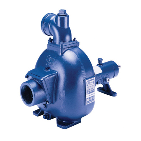
- Page 1 OM−00956−OE03 June 29, 1993 INSTALLATION, OPERATION, AND MAINTENANCE MANUAL WITH PARTS LIST 80 SERIES PUMP MODEL 86A2−F300 THE GORMAN-RUPP COMPANY D MANSFIELD, OHIO GORMAN-RUPP OF CANADA LIMITED ST. THOMAS, ONTARIO, CANADA Printed in U.S.A. Copyright by the Gorman-Rupp Company...
- Page 2 The engine exhaust from this product contains chemicals known to the State of California to cause cancer, birth defects or other reproductive harm.
-
Page 3: Table Of Contents
TABLE OF CONTENTS INTRODUCTION ..........PAGE I −... - Page 4 TABLE OF CONTENTS (continued) Pump Model ............PAGE E −...
-
Page 5: Introduction
The basic material of construction Rupp pump. for all wetted parts is gray iron and steel. This pump is an 80 Series, semi-open impeller, self- priming centrifugal model with a suction check If there are any questions regarding the pump or its valve. -
Page 6: Safety - Section A
80 SERIES OM−00956−03 SAFETY − SECTION A This information applies to 80 Series for use in lifting the pump assembly only. Suction and discharge hoses and Engine Driven pumps. Refer to the man- piping must be removed from the pump ual accompanying the engine before at- before lifting. - Page 7 OM−00956−03 80 SERIES Fuel used by internal combustion en- Never tamper with the governor to gain gines presents an extreme explosion more power. The governor establishes and fire hazard. Make certain that all safe operating limits that should not be fuel lines are securely connected and exceeded.
-
Page 8: Installation − Section Bpage B
80 SERIES OM−00956−03 INSTALLATION − SECTION B Review all SAFETY information in Section A. to the pump is critical to performance and safety, be sure to limit the incoming pressure to 50% of the Since pump installations are seldom identical, this maximum permissible operating pressure. -
Page 9: Battery Specifications And Installation
OM−00956−03 80 SERIES ing, check for loose hardware at mating sur- sion. Connect and tighten the positive cable first, faces. then the negative cable. c. Carefully read all tags, decals, and markings POSITIONING PUMP on the pump assembly, and perform all duties indicated. -
Page 10: Suction And Discharge Piping
80 SERIES OM−00956−03 To ensure sufficient lubrication and fuel supply to suction and discharge ports and install the lines. the engine, do not position the pump and engine Installation closer to the pump may result in erratic more than 15_ off horizontal for continuous opera- readings. -
Page 11: Suction Lines In Sumps
OM−00956−03 80 SERIES Suction Lines In Sumps of one or both pumps. To avoid this, position the suction inlets so that they are separated by a dis- tance equal to at least 3 times the diameter of the If a single suction line is installed in a sump, it suction pipe. -
Page 12: Valves
80 SERIES OM−00956−03 Valves Bypass Lines If a throttling valve is desired in the discharge line, If a system check valve is used due to high dis- use a valve as large as the largest pipe to minimize charge head, it may be necessary to vent trapped friction losses. -
Page 13: Operation − Section C
OM−00956−03 80 SERIES OPERATION − SECTION C Review all SAFETY information in Section A. not prime when dry. Extended operation of a dry pump will destroy the seal assembly. Follow the instructions on all tags, labels and decals attached to the pump. -
Page 14: Operation
OM−00956−03 80 SE- RIES OPERATION pump components will deteriorate, and the liquid could come to a boil, build pressure, and cause the pump casing to rupture or explode. Pump speed and operating condition Leakage points must be within the continuous per- No leakage should be visible at pump mating sur- formance range shown on the curve. -
Page 15: Pump Vacuum Check
OM−00956−03 80 SERIES drop. If a vacuum suction gauge has been in- After stopping the pump, switch off the engine igni- stalled, monitor and record the readings regularly tion and remove the key or take other precautions to detect strainer blockage. -
Page 16: Troubleshooting − Section D
OM−00956−03 80 SERIES TROUBLESHOOTING − SECTION D Review all SAFETY information in Section A. Before attempting to open or service the pump: 1. Familiarize yourself with this manual. 2. Switch off the engine ignition and re- move the key or take other precau- tions to ensure that the pump will re- main inoperative. - Page 17 OM−00956−03 80 SERIES TROUBLE POSSIBLE CAUSE PROBABLE REMEDY PUMP STOPS OR Suction intake not submerged at Check installation and correct sub- FAILS TO DELIVER proper level or sump too small. mergence as needed. RATED FLOW OR Impeller or other wearing parts worn Replace worn or damaged parts.
-
Page 18: Pump Maintenance And Repair - Section Epage E
80 SERIES OM−00956−03 PUMP MAINTENANCE AND REPAIR - SECTION E MAINTENANCE AND REPAIR OF THE WEARING PARTS OF THE PUMP WILL MAINTAIN PEAK OPERATING PERFORMANCE. C-6-79-R STANDARD PERFORMANCE FOR PUMP MODEL 86A2−F300 Based on 70_ F (21_ C) clear water at sea level Contact the Gorman-Rupp Company to verify per- formance or part numbers. - Page 19 OM−00956−03 80 SE- RIES SECTION DRAWING Figure 1. Pump Model 86A2−F300 PAGE E − 2 MAINTENANCE & REPAIR...
-
Page 20: Parts Lists
80 SERIES OM−00956−03 PARTS LIST Pump Model 86A2−F300 (From S/N 1022351 up) If your pump serial number is followed by an N", your pump is NOT a standard production model. Contact the Gorman-Rupp Company to verify part numbers. ITEM PART NAME PART MAT’L... - Page 21 OM−00956−03 80 SE- RIES SECTION DRAWING Figure 2. Pump End Assembly 86A2−(SAE 3/10) PAGE E − 4 MAINTENANCE & REPAIR...
- Page 22 80 SERIES OM−00956−03 PARTS LIST Pump End Assembly 86A2−(SAE 3/10) ITEM PART NAME PART MAT’L ITEM PART NAME PART MAT’L NUMBER CODE NUMBER CODE PUMP CASING 7267 10010 BEARING CONE S1087 −−−−− 1 IMPELLER 2521B 10010 BEARING CLOSURE 10010 STUD...
- Page 23 OM−00956−03 80 SE- RIES SECTION DRAWING Figure 3. Drive Assembly For Pump End 86A2−(SAE 3/10) ITEM PART MAT’L PART NAME NUMBER CODE COUPLING KIT 48112−001 −−−−− −BUSHING 24131−345 −−−−− −COUPLING ASSEMBLY 44165−011 −−−−− −LOCKWASHER 21171−536 −−−−− −SOCKET HD CAPSCREW BD0606 1/2 15991 HEX HD CAPSCREW B0606...
- Page 24 80 SERIES OM−00956−03 Suction Check Valve Removal PUMP AND SEAL DISASSEMBLY AND REASSEMBLY (Figure 2) Before attempting to service the pump, remove the Review all SAFETY information in Section A. pump casing drain plug (42) and drain the pump. Clean and reinstall the drain plug.
- Page 25 OM−00956−03 80 SERIES er, and seal spring from the seal plate. Remove the only. Suction and discharge hoses and inner seal washer, packing ring, stationary seat piping must be removed from the pump and rotating element. before lifting. Inspect the seal liner (14) for wear or grooves that...
- Page 26 80 SERIES OM−00956−03 is not recommended. These operations flammable. Use them only in a well ven- tilated area free from excessive heat, should be performed only in a properly- sparks, and flame. Read and follow all equipped shop by qualified personnel.
- Page 27 OM−00956−03 80 SERIES the shaft, it is recommended that bearings be cleaned and inspected in place. It is strongly recommended that the bearings be replaced any time the shaft and bear- When installing the bearing cups into the ings are removed.
- Page 28 80 SERIES OM−00956−03 Seal Reassembly and Installation coupling is mounted as shown in Figure 3. This is critical. If the coupling is not prop- (Figures 2 and 4) erly positioned on the shaft, the coupling parts may not fully engage, or a pre-load...
- Page 29 OM−00956−03 80 SERIES GREASE SEAL PIPING PLATE PACKING RINGS SEAL LINER IMPEL- Ç SEAL WASHER Ç Ç STATIONARY SEAL SEATS IMPELLER SHAFT ROTATING IMPELLER ELEMENTS SHIMS Ç Ç Ç SPACER SLEEVE SPRING STATIONARY WASHERS Figure 4. GS1250 Seal Assembly Slide the seal plate onto the shaft until fully seated against the intermediate.
- Page 30 80 SERIES OM−00956−03 Install the outboard rotating element with the A clearance of .010 to .020 inch (0,3 to 0,5 mm) be- tween the impeller and the wear plate is also rec- chamfered side facing the impeller. ommended for maximum pump efficiency. This...
- Page 31 OM−00956−03 80 SERIES (Figure 2) with No. 2 lithium base grease until grease es- capes from the relief hole. Turn the grease cup arm Before starting the pump, remove the fill plug as- counterclockwise until it is at the top of the stem;...
- Page 32 80 SERIES OM−00956−03 For cold weather operation, consult the factory or a lubricant supplier for the recommended grade of lubricant. Engine Consult the literature supplied with the engine, or contact your local Ford engine representative. MAINTENANCE & REPAIR PAGE E − 15...
- Page 33 For U.S. and International Warranty Information, Please Visit www.grpumps.com/warranty or call: U.S.: 419−755−1280 International: +1−419−755−1352 For Canadian Warranty Information, Please Visit www.grcanada.com/warranty or call: 519−631−2870 THE GORMAN-RUPP COMPANY D MANSFIELD, OHIO GORMAN-RUPP OF CANADA LIMITED ST. THOMAS, ONTARIO, CANADA...
Need help?
Do you have a question about the 80 Series and is the answer not in the manual?
Questions and answers