
Related Manuals for GORMAN-RUPP PUMPS 82D1-L70W FT4-X


Summary of Contents for GORMAN-RUPP PUMPS 82D1-L70W FT4-X
- Page 1 OM-07504-01 March 2, 2022 INSTALLATION, OPERATION, AND MAINTENANCE MANUAL WITH PARTS LIST 80 SERIES PUMP MODEL 82D1-L70W FT4-X GORMAN‐RUPP PUMPS www.grpumps.com 2022 Gorman‐Rupp Pumps Printed in U.S.A.
- Page 2 Register your new Gorman‐Rupp pump online at www.grpumps.com Valid serial number and e‐mail address required. The engine exhaust from this product contains chemicals known to the State of California to cause cancer, birth defects or other reproductive harm. RECORD YOUR PUMP MODEL AND SERIAL NUMBER Please record your pump model and serial number in the spaces provided below.
-
Page 3: Table Of Contents
TABLE OF CONTENTS INTRODUCTION ..........PAGE I - 1 SAFETY ‐... - Page 4 TABLE OF CONTENTS (continued) Pump Parts Only ............PAGE E - 5 PUMP AND SEAL DISASSEMBLY AND REASSEMBLY .
-
Page 5: Introduction
80 SERIES OM-07504 INTRODUCTION Thank You for purchasing a Gorman‐Rupp pump. HAZARD AND INSTRUCTION Read this manual carefully to learn how to safely DEFINITIONS install and operate your pump. Failure to do so could result in personal injury or damage to the The following are used to alert maintenance per... -
Page 6: Safety - Section A
80 SERIES OM-07504 SAFETY ‐ SECTION A This information applies to 80 Series en mable atmosphere free of combustible hazards. It cannot be further modified gine driven pumps. Refer to the manual without affecting performance and safe accompanying the engine before at ty factors. - Page 7 OM-07504 80 SERIES gaged to be ejected with great force. al low the pump to cool before servicing. Fuel used by internal combustion en gines presents an extreme explosion and fire hazard. Make certain that all Overheated pumps can cause severe fuel lines are securely connected and burns and injuries.
-
Page 8: Installation - Section B
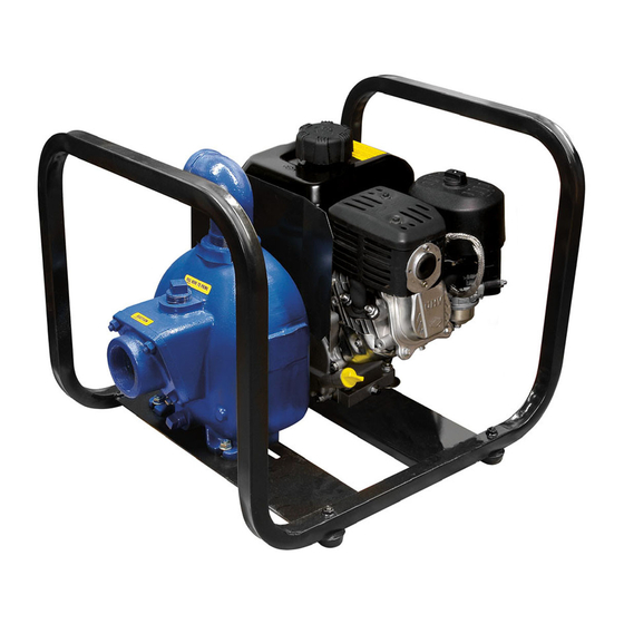
[ 533,4 ] [ 711,2 ] 22.09 APPROX [ 561,1 ] Figure 1. Pump Model 82D1-L70W FT4-X PREINSTALLATION INSPECTION a. Inspect the pump and engine for cracks, dents, damaged threads, and other obvious damage. The pump assembly was inspected and tested be... -
Page 9: Positioning Pump
OM-07504 80 SERIES ing, check for loose hardware at mating sur Mounting faces. Locate the pump in an accessible place as close as practical to the liquid being pumped. Level mount c. Carefully read all tags, decals, and markings ing is essential for proper operation. on the pump assembly, and perform all duties indicated. -
Page 10: Gauges
80 SERIES OM-07504 place by tightening the flange bolts and/or cou three or four times the cross section of the suction plings. line, and the openings will not permit passage of solids larger than the solids handling capability of Lines near the pump must be independently sup the pump. -
Page 11: Discharge Lines
OM-07504 80 SERIES by installing a standard pipe increaser fitting at the submergence using the following formula based end of the suction line. The larger opening size will on the increased opening size (area or diameter). reduce the inlet velocity. Calculate the required Figure 2. -
Page 12: Grounding
80 SERIES OM-07504 GROUNDING To eliminate electrostatic build‐up by the liquid be ing pumped, the unit must be grounded by attach Inspect and test the ground wire assembly ing the ground wire assembly to a ground rod. In stall the ground rod in accordance with the Nation for conductivity. -
Page 13: Operation - Section C
OM-07504 80 SERIES OPERATION - SECTION C Review all SAFETY information in Section A. not prime when dry. Extended operation of a dry pump will destroy the seal assembly. Follow the instructions on all tags, labels and Add liquid to the pump casing when: decals attached to the pump. -
Page 14: Lines Without A Bypass
OM-07504 80 SERIES open the discharge throttling valve. Liquid will then gaged to be ejected with great force. al continue to circulate through the bypass line while low the pump to cool before servicing. the pump is in operation. Strainer Check Lines Without a Bypass If a suction strainer has been shipped with the pump or installed by the user, check the strainer... -
Page 15: Cold Weather Preservation
OM-07504 80 SERIES shock waves can be transmitted to the pump and Cold Weather Preservation piping system. Close all connecting valves slowly. In below freezing conditions, drain the pump to On engine driven pumps, reduce the throttle prevent damage from freezing. Also, clean out any speed slowly and allow the engine to idle briefly be... -
Page 16: Troubleshooting - Section D
80 SERIES OM-07504 TROUBLESHOOTING - SECTION D Review all SAFETY information in Section A. Before attempting to open or service the pump: 1. Familiarize yourself with this manual. 2. Shut down the engine and take pre cautions to ensure that the pump will remain inoperative. - Page 17 OM-07504 80 SERIES TROUBLE POSSIBLE CAUSE PROBABLE REMEDY Air leak in suction line. Correct leak. PUMP STOPS OR FAILS TO DELIVER Lining of suction hose collapsed. Replace suction hose. RATED FLOW OR Suction intake not submerged at Check installation and correct PRESSURE (cont.) proper level or sump too small.
- Page 18 80 SERIES OM-07504 equipped) between regularly scheduled inspec PREVENTIVE MAINTENANCE tions can indicate problems that can be corrected Since pump applications are seldom identical, and before system damage or catastrophic failure oc pump wear is directly affected by such things as curs.
-
Page 19: Pump Maintenance And Repair - Section E
OM-07504 PUMP MAINTENANCE AND REPAIR ‐ SECTION E MAINTENANCE AND REPAIR OF THE WEARING PARTS OF THE PUMP WILL MAINTAIN PEAK OPERATING PERFORMANCE. STANDARD PERFORMANCE FOR PUMP MODEL 82D1-L70W FT4-X Based on 70 F (21 C) clear water (corrected to Contact the Gorman‐Rupp Company to verify per... - Page 20 OM-07504 80 SERIES PARTS PAGE ILLUSTRATION DETAIL A Figure 1. Pump Model 82D1-L70W FT4-X PAGE E - 2 MAINTENANCE & REPAIR...
-
Page 21: Parts Lists
80 SERIES OM-07504 PARTS LIST Pump Model 82D1-L70W FT4-X (From S/N 1764038 Up) If your pump serial number is followed by an “N”, your pump is NOT a standard production model. Contact the Gorman‐Rupp Company to verify part numbers. ITEM... - Page 22 OM-07504 80 SERIES ILLUSTRATION Î Î Î Î Î Ï Ï Ï Ï Î Î Î Î Î Î Î Î Î Î Î Î Î Î Î Î Î Î Î Î Î Î Î Î Î Ì Ì Ì...
- Page 23 80 SERIES OM-07504 PARTS LIST Pump Parts Only ITEM PART PART NAME NUMBER PUMP CASING SEE NOTE BELOW FILL PLUG ASSY 48271-062 PIPE NIPPLE THA3212 15079 PIPE ELBOW R32 11999 HEX NUT D06 15991 HEX HEAD CAP SCREW 22645-132 LOCK WASHER 21171-510 INTERMEDIATE BRACKET 38264-334 10000...
- Page 24 OM-07504 80 SERIES PUMP AND SEAL DISASSEMBLY AND REASSEMBLY Review all SAFETY information in Section A. The engine used in this pump is not standard. It has been modified for use in handling gasoline and other petroleum Follow the instructions on all tags, label and de products in a well‐ventilated, non‐flam...
- Page 25 80 SERIES OM-07504 (Figure 2) 6. Vent the pump slowly and cau tiously. Remove the nuts (5) securing the pump casing to 7. Drain the pump. the intermediate. Separate the parts by pulling the casing straight away from the intermediate. If shims have been used under the mounting feet to level the pump casing, tie and tag these shims.
- Page 26 OM-07504 80 SERIES dowel or other suitable tool to press the stationary The seal is not normally reused because wear pat seat and O‐ring out of the intermediate bore from terns on the finished faces cannot be realigned the back side of the intermediate. during reassembly.
- Page 27 80 SERIES OM-07504 RETAINER SPRING O‐RING SPRING CENTERING WASHER STATIONARY IMPELLER SEAT SHIMS SHAFT IMPELLER SHAFT SLEEVE IMPELLER INTERMEDIATE ROTATING ELEMENT BELLOWS Figure 3. Seal Assembly gine during disassembly, subassemble the O‐ring into the stationary seat and use a piece of plastic pipe to press the seat into the intermediate bore un...
- Page 28 OM-07504 80 SERIES shims (13) as previously removed, and screw the Position the check valve assembly (25) in the suc impeller onto the shaft until tight. tion port with the large weight toward the inside of the pump. Install the suction flange (24) and se A clearance of .010 to .020 inch (0,25 to 0,51 mm) cure with the nuts (5).
- Page 29 For Warranty Information, Please Visit www.grpumps.com/warranty or call: U.S.: 419-755-1280 Canada: 519-631-2870 International: +1-419-755-1352 GORMAN‐RUPP PUMPS...
Need help?
Do you have a question about the 82D1-L70W FT4-X and is the answer not in the manual?
Questions and answers