GORMAN-RUPP PUMPS 80 Series Installation, Operation, And Maintenance Manual With Parts List
Hide thumbs
Also See for 80 Series:
Table of Contents
Advertisement
Quick Links
ACEGU
INSTALLATION, OPERATION,
AND MAINTENANCE MANUAL
JS4D20−E9.4 230V 3P
JS4D20−E9.4 230V 3P
JS4D20−E9.4 230V 3P
THE GORMAN-RUPP COMPANY D MANSFIELD, OHIO
GORMAN-RUPP OF CANADA LIMITED
WITH PARTS LIST
80 SERIES PUMP
MODELS
MODEL
82E2−GX270
www.gormanrupp.com
D
ST. THOMAS, ONTARIO, CANADA
e
2010 The Gorman-Rupp Company
OM−06217−01
March 22, 2010
JS4D20−E9.4 230V 3P
JS4D20−E9.4 230V 3P
JS4D20−E9.4 230V 3P
Printed in U.S.A.
Advertisement
Table of Contents

Related Manuals for GORMAN-RUPP PUMPS 80 Series


Summary of Contents for GORMAN-RUPP PUMPS 80 Series
- Page 1 ACEGU OM−06217−01 March 22, 2010 INSTALLATION, OPERATION, AND MAINTENANCE MANUAL WITH PARTS LIST 80 SERIES PUMP MODELS MODEL JS4D20−E9.4 230V 3P JS4D20−E9.4 230V 3P 82E2−GX270 JS4D20−E9.4 230V 3P JS4D20−E9.4 230V 3P JS4D20−E9.4 230V 3P JS4D20−E9.4 230V 3P THE GORMAN-RUPP COMPANY D MANSFIELD, OHIO www.gormanrupp.com...
- Page 2 Register your new Gorman-Rupp pump online at www.grpumps.com Valid serial number and e-mail address required. The engine exhaust from this product contains chemicals known to the State of California to cause cancer, birth defects or other reproductive harm. RECORD YOUR PUMP MODEL AND SERIAL NUMBER Please record your pump model and serial number in the spaces provided below.
-
Page 3: Table Of Contents
TABLE OF CONTENTS INTRODUCTION ..........PAGE I −... - Page 4 TABLE OF CONTENTS (continued) PUMP AND SEAL DISASSEMBLY AND REASSEMBLY ......PAGE E − 6 Suction Check Valve Removal and Disassembly .
-
Page 5: Introduction
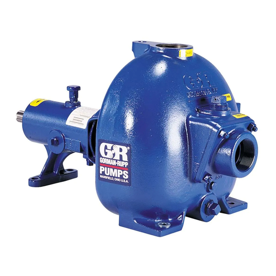
This pump is an 80 Series, semi-open impeller, self- priming centrifugal model with a suction check valve. It is close-coupled to a single cylinder, air cooled Honda gasoline engine. -
Page 6: Safety - Section A
80 SERIES OM−06217 SAFETY - SECTION A This information applies to 80 Series en- gine driven pumps. Refer to the manual accompanying the engine before at- tempting to begin operation. This pump is designed to handle most non-volatile, non-flammable liquids This manual will alert personnel to containing specified entrained solids. - Page 7 OM−06217 80 SERIES gines presents an extreme explosion and fire hazard. Make certain that all fuel lines are securely connected and Overheated pumps can cause severe free of leaks. Never refuel a hot or run- burns and injuries. If overheating of the ning engine.
-
Page 8: Installation − Section Bpage B
80 SERIES OM−06217 INSTALLATION − SECTION B Review Safety information in Section A. to the pump is critical to performance and safety, be sure to limit the incoming pressure to 50% of the Since pump installations are seldom identical, this... -
Page 9: Preinstallation Inspection Page B
OM−06217 80 SERIES tag on the unit packaging for the actual weight, and PREINSTALLATION INSPECTION use lifting equipment with appropriate capacity. Drain the pump and remove all customer-installed The pump assembly was inspected and tested be- equipment such as suction and discharge hoses fore shipment from the factory. -
Page 10: Line Configuration
80 SERIES OM−06217 Line Configuration stalled with the flat part of the reducers uppermost to avoid creating air pockets. Valves are not nor- Keep suction and discharge lines as straight as mally used in suction lines, but if a valve is used, possible to minimize friction losses. -
Page 11: Suction Line Positioning
OM−06217 80 SERIES of the suction pipe. The baffle will allow entrained critical to efficient pump operation. Figure 2 shows air to escape from the liquid before it is drawn into recommended minimum submergence vs. veloc- the suction inlet. ity. -
Page 12: Bypass Lines
80 SERIES OM−06217 stalled in the discharge line to protect the pump Bypass Lines from excessive shock pressure and reverse rota- If a system check valve is used due to high dis- tion when it is stopped. charge head, it may be necessary to vent trapped air from the top of the pump during the priming process. -
Page 13: Operation − Section C
OM−06217 80 SERIES OPERATION − SECTION C Review all information in Safety, Section A. Add liquid to the pump casing when: 1. The pump is being put into service for the Follow the instructions on all tags, labels and first time. -
Page 14: Lines Without A Bypass
OM−06217 80 SERIES line. Air from the suction line will be discharged through the bypass line back to the wet well during the priming cycle. When the pump is fully primed Do not remove plates, covers, gauges, and liquid is flowing steadily from the bypass line, pipe plugs, or fittings from an over- open the discharge throttling valve. -
Page 15: Stopping
OM−06217 80 SERIES Cold Weather Preservation STOPPING Never halt the flow of liquid suddenly. If the liquid being pumped is stopped abruptly, damaging shock waves can be transmitted to the pump and In below freezing conditions, drain the pump to piping system. -
Page 16: Troubleshooting − Section Dpage D
80 SERIES OM−06217 TROUBLESHOOTING − SECTION D Review all Safety information in Section A. Before attempting to open or service the pump: 1. Familiarize yourself with this manual. 2. Shut down the engine and discon- nect the spark plug wire to ensure that the pump will remain inopera- tive. - Page 17 OM−06217 80 SERIES TROUBLE POSSIBLE CAUSE PROBABLE REMEDY PUMP STOPS OR Air leak in suction line. Correct leak. FAILS TO DELIVER Lining of suction hose collapsed. Replace suction hose. RATED FLOW OR PRESSURE Leaking or worn seal or pump gasket.
- Page 18 80 SERIES OM−06217 equipped) between regularly scheduled inspec- PREVENTIVE MAINTENANCE tions can indicate problems that can be corrected Since pump applications are seldom identical, and before system damage or catastrophic failure oc- pump wear is directly affected by such things as curs.
-
Page 19: Pump Maintenance And Repair - Section Epage E
80 SERIES OM−06217 PUMP MAINTENANCE AND REPAIR - SECTION E MAINTENANCE AND REPAIR OF THE WEARING PARTS OF THE PUMP WILL MAINTAIN PEAK OPERATING PERFORMANCE. STANDARD PERFORMANCE FOR PUMP MODEL 82E2−GX270 Based on 70_ F (21_ C) clear water at sea level Contact the Gorman-Rupp Company to verify per- with minimum suction lift. - Page 20 OM−06217 80 SERIES SECTION DRAWING PARTS PAGE Figure 1. Pump Model 82E2−GX270 PAGE E − 2 MAINTENANCE & REPAIR...
-
Page 21: Parts Lists
80 SERIES OM−06217 PARTS LIST Pump Model 82E2−GX270 (From S/N 1451696 Up) If your pump serial number is followed by an N", your pump is NOT a standard production model. Contact the Gorman-Rupp Company to verify part numbers. ITEM PART MAT’L... - Page 22 OM−06217 80 SERIES SECTION DRAWING Figure 2. Pump End 82E2−(GX270) PAGE E − 4 MAINTENANCE & REPAIR...
- Page 23 80 SERIES OM−06217 PARTS LIST Pump End 82E2−(GX270) ITEM PART NAME PART MAT’L ITEM PART NAME PART MAT’L NUMBER CODE NUMBER CODE PUMP CASING 6851C 10010 FIBER WASHER KF06 18040 IMPELLER 6709 10010 STUD C0606 15991 GREASE SEAL ASSY GS1000 −−−...
- Page 24 OM−06216 80 SERIES PUMP AND SEAL DISASSEMBLY 4. Check the temperature before opening any covers, plates, or AND REASSEMBLY plugs. 5. Close the suction and discharge Review Safety information in Section A. valves. 6. Vent the pump slowly and cau- Follow the instructions on all tags, label and de- tiously.
- Page 25 80 SERIES OM−06216 Tie and tag any leveling shims used under the cas- diate, and use a suitably sized dowel to press the ing mounting feet to ease reassembly. seal components from the intermediate. Inspect the wear plate (12) and replace if badly scored or worn.
- Page 26 OM−06216 80 SERIES Inspect the seal components for wear, scoring, tilated area free from excessive heat, grooves, and other damage that might cause leak- sparks, and flame. Read and follow all age. Clean and polish the seal spacer sleeve, or re- precautions printed on solvent contain- place it if there are nicks or cuts on either end.
- Page 27 80 SERIES OM−06216 Subassemble the inboard stationary seat, packing Replace the fiber washer (17) if badly worn or com- ring and stationary washer. Press this unit into the pressed. lubricated seal liner until the seal faces contact. A Install the same thickness of pump casing gaskets...
- Page 28 OM−06216 80 SERIES Fill the pump casing with clean liquid. Reinstall the with No. 2 lithium base grease until grease es- fill plug (27, Figure 2) and tighten it. capes from the relief hole. Turn the grease cup arm counterclockwise until it is at the top of the stem;...
- Page 29 For U.S. and International Warranty Information, Please Visit www.grpumps.com/warranty or call: U.S.: 419−755−1280 International: +1−419−755−1352 For Canadian Warranty Information, Please Visit www.grcanada.com/warranty or call: 519−631−2870 THE GORMAN-RUPP COMPANY D MANSFIELD, OHIO GORMAN-RUPP OF CANADA LIMITED ST. THOMAS, ONTARIO, CANADA...
Need help?
Do you have a question about the 80 Series and is the answer not in the manual?
Questions and answers