
Related Manuals for tams elektronik 53-02015


Summary of Contents for tams elektronik 53-02015
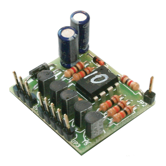
- Page 1 Manual Light Computer Item no. 53-02015 - 53-02236 For all kits and ready-built modules of the LC series tams elektronik n n n...
-
Page 2: Table Of Contents
11. EU declaration of conformity............33 12. Declarations conforming to the WEEE directive......33 © 12/2015 Tams Elektronik GmbH All rights reserved. No part of this publication may be reproduced or transmitted in any form or by any means, electronic or mechanical, including photocopying, without prior permission in writing from Tams Elektronik GmbH. -
Page 3: Getting Started
LC modules English 1. Getting started How to use this manual This manual gives step-by-step instructions for safe and correct assembly of the kit and fitting and connecting of the ready-built module, and operation. Before you start, we advise you to read the whole manual, particularly the chapter on safety instructions and the checklist for trouble shooting. - Page 4 English LC modules Checking the package contents Please make sure that your package contains: one kit, containing the components listed in the parts list (page 19) and one PCB or one ready-built module, two socket terminal strips (1 x 3-pole, 1 x 5-pole), ...
- Page 5 LC modules English In addition, you possibly need for the following versions of the LC- modules: LC-module 16: For the connection of accessories with a current consumption of more than 100 mA to output 1: a monostable relay 1xUm 12 V (e.g. item-no. 84-61010-01) and a protective diode 1N400x, x >...
-
Page 6: Safety Instructions
English LC modules 2. Safety instructions Mechanical hazards Cut wires can have sharp ends and can cause serious injuries. Watch out for sharp edges when you pick up the PCB. Visibly damaged parts can cause unpredictable danger. Do not use damaged parts: recycle and replace them with new ones. - Page 7 LC modules English Fire risk Touching flammable material with a hot soldering iron can cause fire, which can result in injury or death through burns or suffocation. Connect your soldering iron or soldering station only when actually needed. Always keep the soldering iron away from inflammable materials.
-
Page 8: Safe And Correct Soldering
English LC modules In schools, training centres, clubs and workshops, assembly must be supervised by qualified personnel. In industrial institutions, health and safety regulations applying to electronic work must be adhered to. 3. Safe and correct soldering Caution: Incorrect soldering can cause dangers through fires and heat. Avoid these dangers by reading and following the directions given in the chapter Safety instructions. - Page 9 LC modules English To make a good soldering joint you must use a clean and unoxidised soldering tip. Clean the soldering tip with a damp piece of cloth, a damp sponge or a piece of silicon cloth. Cut the wires after soldering directly above the soldering joint with a side cutter.
-
Page 10: Operation Overview
English LC modules 4. Operation overview The Light Computer is controlled by a micro controller. The program stored in the micro controller controls the five outputs of the module. Sequence and timing are different with the various versions. The LC module has a switching input (JP2) which has effects on the program sequence with some versions. - Page 11 LC modules English LC-4 "Building site flasher": At the five outputs a running light sequence is created. If the input JP2 is switched to earth, the light sequence switches off after the completion of the program. If the input remains open, the program repeats continuously. LC-5 "Flickering flame": At the five outputs an irregular light pattern is created.
- Page 12 English LC modules LC-8 "Advertising light 4": Fusion of the advertising lights 1 to 3, coming on one after the other. If the input JP2 is switched to earth, the light sequence switches off after the completion of the active part of the program.
- Page 13 LC modules English goes on for a short time at irregular intervals. By the end of the program the lights in the bedroom (output 5) and in the bathroom go on for some time, the bulbs connected to outputs 2 and 3 switch off. Program 2: In the entrance-hall (output 1) the light goes on for a short time at irregular intervals.
- Page 14 English LC modules LC-16 "Dim switch for street lamps": The input JP2 is switched on and off automatically via a light sensitive switch. The sensitivity of the switch is set via a trimpot. Four outputs are designed for the connection of street lamps. The street lamps are getting brighter gradually after being switched on and obtain their maximum brightness after about one minute.
- Page 15 LC modules English In the program "moving vehicle": The front and back lights are always switched on. It is possible to connect a loudspeaker as a horn (not included) to output 3, the volume can be reduced by connecting a series resistor (approx.
- Page 16 English LC modules LC-21 "Funfair flow effect lighting 1": The 5 outputs generate a light flow sequence. After the first run through the output 5 stays on, after the second run through the output 4, and so on, so that after 5 cycles all connected lamps or LEDS are switched on.
-
Page 17: Technical Specifications
LC modules English 5. Technical specifications Supply voltage 10 – 18 Volt a.c. or d.c. voltage Current consumption (without 20 mA connected devices) approx. Max. total current 500 mA Number of outputs Max. current per output 100 mA Number of switching inputs Protected to IP 00 Ambient temperature in use... - Page 18 English LC modules Resistors Resistors reduce current. The value of resistors for smaller power ratings is indicated through colour rings. Every colour stands for another figure. Carbon film resistors have 4 colour rings. The 4th ring (given in brackets here) indicates the tolerance of the resistor (gold = 5 %).
- Page 19 LC modules English Transistors Transistors are current amplifiers which convert low signals into stronger ones. There are several types in different package forms available. The type designation is printed on the component. Transistors for a low power rating (e.g. BC types, BS types) have a package in form of a half zylinder (SOT- package).
- Page 20 English LC modules PCB layout and parts list Resistors R1 - R5 10 k R6, R8 1 k Diodes 1N400x, x=2...7 1N4148 Zener diode ZD 5,1 V Electrolytic C1, C2 100 µF/25 V capacitors Transistors T1 - T5 BC547B Micro-controller IC1 12F508A-I/P IC-socket IC-1...
- Page 21 LC modules English Resistors Mounting orientation of no importance. Diodes, Zener Observe the polarity! diodes The negative end of the diodes is marked with a ring. This is shown in the PCB layout. IC socket Mount the socket that way, the marking on the socket shows in the same direction as the marking on the PCB board.
-
Page 22: Connecting The Lc Module
English LC modules 7. Connecting the LC module Connect the power supply, the light bulbs, LEDs or other accessories and if neccessary switches or push-buttons, according to the following list and connecting diagrams, to the LC module. Follow the appended instructions below as well. - Page 23 LC modules English Use of the switching input JP2 According to the version you can control the program flow or choose one of two different program variants via the switching input JP2. According to the version and to the intended mode of operation you can use switches, push-buttons or fixed solder connections.
- Page 24 English LC modules Connecting light bulbs As a rule you can connect one or two bulbs to one output. Bulbs are not polarized. Connect one side to the output, the other to the return conductor. Caution: The maximum current of 100 mA per output should not be exceeded.
- Page 25 LC modules English Parallel connection of LEDs With a parallel connection each LED has to be connected via it´s own series resistor to the output. The total current at the output results from summing up the current of each single LED. The current consumption of one LED depends on the value of the series resistor.
- Page 26 English LC modules Examples for parallel connection of LEDs: Power supply Series Current per max. number resistors of LEDs per output transformer (~) | 12 V 1,5 kOhm 10 mA transformer (~) | 12 V 820 Ohm 20 mA transformer (~) | 15-16 V 2,2 kOhm 10 mA transformer (~) | 15-16 V 1 kOhm 20 mA...
- Page 27 LC modules English Examples for serial connection of LEDs: Nominal voltage Operating Forward voltage Max. number of transformer (~)* voltage * appr. of the LED* LEDs* per output 12 V 17 V 16 V 22 V 18 V 25 V Nominal voltage and operating voltage: The operating voltage with a.c.
-
Page 28: Connecting The Lc-16
English LC modules Tip: Connecting many LEDs to one LC module If you want to connect a great number of LEDs to one LC module (e.g. with advertising lights or funfair lights), best connect them as follows: Connect so many LEDs in series as possible with the available operating voltage. - Page 29 LC modules English Relay Diode, 1N400x, x = 2...7 DS-1 Dim switch Light depending resistor Ausgang 1 Additional accessories Ausgang 2-5 Street lamps Connecting an additional load (LC-16) With the LC-16 the output 1 is designed for the connection of additional accessories (e.g.
-
Page 30: Check List For Troubleshooting
English LC modules 9. Check list for troubleshooting Parts are getting too hot and/or start to smoke. Disconnect the system from the mains immediately! Possible cause: one or more components are soldered incorrectly. à In case you have mounted the module from a kit, perform a visual check (à... - Page 31 LC modules English Hotline: If problems with your module occur, our hotline is pleased to help you (mail address on the last page). Repairs: You can send in a defective module for repair (address on the last page). In case of guarantee the repair is free of charge for you. With damages not covered by guarantee, the maximum fee for the repair is the difference between the price for the ready-built module and the kit according to our valid price list.
-
Page 32: Guarantee Bond
English LC modules 10. Guarantee bond For this product we issue voluntarily a guarantee of 2 years from the date of purchase by the first customer, but in maximum 3 years after the end of series production. The first customer is the consumer first purchasing the product from us, a dealer or another natural or juristic person reselling or mounting the product on the basis of self- employment. -
Page 33: Eu Declaration Of Conformity
LC modules English 11. EU declaration of conformity This product conforms with the EC-directives mentioned below and is therefore CE certified. 2004/108/EG on electromagnetic. Underlying standards: EN 55014-1 and EN 61000-6-3. To guarantee the electromagnetic tolerance in operation you must take the following precautions: ... - Page 34 Information and tips: http://www.tams-online.de Warranty and service: Tams Elektronik GmbH Fuhrberger Straße 4 DE-30625 Hannover fon: +49 (0)511 / 55 60 60 fax: +49 (0)511 / 55 61 61 e-mail: modellbahn@tams-online.de...
Need help?
Do you have a question about the 53-02015 and is the answer not in the manual?
Questions and answers