
Related Manuals for tams elektronik S88-2


Summary of Contents for tams elektronik S88-2
- Page 1 S88-2 s88 Booster Manual Item nos. 44-01205 | 44-01206 | 44-01207 tams elektronik n n n...
- Page 2 © Tams Elektronik GmbH All rights reserved, in particular the right of reproduction, distribution and translation. Copies, reproductions and alterations in any form require the written permission of Tams Elektronik GmbH. We reserve the right to make technical changes. Printing the manual The formatting is optimised for double-sided printing.
-
Page 3: Table Of Contents
S88-2 Contents 1. Getting started......................4 1.1. Contents of the package..................4 1.2. Accessories......................4 1.3. Intended use.......................4 1.4. Safety instructions....................5 1.5. Care........................5 2. Operation overview.......................6 3. Assembling the kit......................7 3.1. Safety instructions....................7 3.2. Soldering properly....................8 3.3. Preparation......................8 3.4. PCB layout and parts list..................10 3.5. -
Page 4: Getting Started
1.1. Contents of the package 1 one kit S88-2 (item no. 44-01205-01), containing the components listed in the parts list (see section 3.4.) and one PCB or 1 ready-built and tested circuit board S88-2 (item no. 44-01206-01) or 1 s88 booster S88-2 in housing (item no. -
Page 5: Safety Instructions
S88-2 1.4. Safety instructions Please note: The s88 booster contains integrated circuits (ICs). These are sensitive to electrostatic charging. Therefore, do not touch these components until you have "discharged" yourself. For this purpose, e.g. a grip on a radiator is sufficient. -
Page 6: Operation Overview
S88-2 tams elektronik 2. Operation overview The s88 booster reduces the interference that can occur during data transmission from the s88 feedback modules to the receiver (control unit, PC via interface or memory) when 6-core cables are used as bus lines. Interference is caused by external electrical signals such as: ... -
Page 7: Assembling The Kit
S88-2 3. Assembling the kit You can skip this section if you have purchased a ready-built module or device. 3.1. Safety instructions Mechanical hazards Cut wires can have sharp ends and can cause serious injuries. Watch out for sharp edges when you pick up the PCB. -
Page 8: Soldering Properly
S88-2 tams elektronik 3.2. Soldering properly Use a soldering iron with temperature control, which you set to approx. 300 °C. Only use electronic solder with a flux. Never use soldering water or soldering grease when soldering electronic circuits. These contain an acid that destroys components and conductor paths. - Page 9 S88-2 Ceramic capacitors Among other things ceramic capacitors are used for filtering interference voltages or as frequency determining parts. Ceramic capacitors are not polarized. Normally they are marked with a three-digit number which indicates the value coded. The number 104 corresponds to the value 100 nF.
-
Page 10: Pcb Layout And Parts List
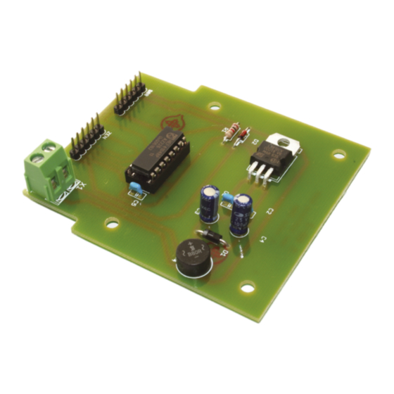
S88-2 tams elektronik Modular terminals Modular terminals are solder-in screw-type terminals. They provide a solder-free and safe connection of the cables to the circuit, which can still be separated any time. 3.4. PCB layout and parts list PCB layout Parts list... -
Page 11: Assembly
S88-2 3.5. Assembly Proceed according to the order given in the list below. First solder the components on the solder side of the PCB and then cut the excess wires with the side cutter. Follow the instructions on soldering in section 3.2. -
Page 12: Performing A Visual Check
S88-2 tams elektronik 3.6. Performing a visual check Perform a visual check after the assembly of the module and remove faults if necessary: Remove all loose parts, wire ends or drops of solder from the PCB. Remove all sharp wire ends. -
Page 13: Connecting The S88 Booster
S88-2 4. Connecting the s88 booster Checking the s88-feedback modules You should check if the s88-feedback modules are working properly before connecting them to s88 booster. See the manual for the s88-feedback modules. That way you can prevent faults occuring after installing the s88 booster due to the s88-feedback modules. - Page 14 S88-2 tams elektronik Connection to the s88 bus Disconnect the first s88-feedback module from the receiver (central unit, interface, memory). Next connect the s88 booster to the receiver and the first s88-feedback module. Caution: You must not interchange the connections to the receiver and the s88 feedback module! If...
-
Page 15: Checklist For Troubleshooting And Error Correction
S88-2 5. Checklist for troubleshooting and error correction Warning: If you notice a strong heat development, immediately disconnect the connection to the supply voltage. Fire hazard! Possible causes: One or more connections are faulty. à Check the connections. -
Page 16: Technical Data
S88-2 tams elektronik 6. Technical data Feedback log Connections to the s88-bus OUT: 6-pole plug connector IN: 6-pole plug connector Electrical characteristics Power supply of the 12 - 18 V AC voltage (own transformer required) s88 booster Warning: If the s88 booster is connected to a... - Page 17 S88-2 Other features Dimensions (approx.) Circuit board: 73 x 80 mm Ready device including housing: 100 x 90 x 35 mm Weight (approx.) Assembled board (ready-made module): 26 g Ready device including housing: 72 g Technical data | 17...
-
Page 18: Warranty, Eu Conformity & Weee
S88-2 tams elektronik 7. Warranty, EU conformity & WEEE 7.1. Guarantee bond For this product we issue voluntarily a guarantee of 2 years from the date of purchase by the first customer, but in maximum 3 years after the end of series production. The first customer is the consumer first purchasing the product from us, a dealer or another natural or juristic person reselling or mounting the product on the basis of self-employment. -
Page 19: Eu Declaration Of Conformity
S88-2 7.2. EU Declaration of Conformity This product fulfils the requirements of the following EU directives and therefore bears the CE marking. 2001/95/EU Product Safety Directive 2015/863/EU on the restriction of the use of certain hazardous substances in electrical and electronic equipment (RoHS) 2014/30/EU on electromagnetic compatibility (EMC Directive). - Page 20 Further Information and Tips: http://www.tams-online.de Warranty and Service: Tams Elektronik GmbH Fuhrberger Straße 4 DE-30625 Hannover fon: +49 (0)511 / 55 60 60 fax: +49 (0)511 / 55 61 61 e-mail: modellbahn@tams-online.de...
Need help?
Do you have a question about the S88-2 and is the answer not in the manual?
Questions and answers