GORMAN-RUPP PUMPS 80 Series Installation, Operation And Maintenance Manual
Hide thumbs
Also See for 80 Series:
Table of Contents
Advertisement
Quick Links
ACEU
INSTALLATION, OPERATION,
AND MAINTENANCE MANUAL
JS4D20−E9.4 230V 3P
JS4D20−E9.4 230V 3P
JS4D20−E9.4 230V 3P
THE GORMAN-RUPP COMPANY D MANSFIELD, OHIO
GORMAN-RUPP OF CANADA LIMITED
WITH PARTS LIST
80 SERIES PUMPS
MODELS
MODELS
82E2−M8
82E2−M8 S/G
www.gormanrupp.com
D
ST. THOMAS, ONTARIO, CANADA
e
Copyright by the Gorman-Rupp Company
January 16, 1990
Rev. A 08-25-04
JS4D20−E9.4 230V 3P
JS4D20−E9.4 230V 3P
JS4D20−E9.4 230V 3P
Printed in U.S.A.
OM-03427-01
Advertisement
Table of Contents

Related Manuals for GORMAN-RUPP PUMPS 80 Series


Summary of Contents for GORMAN-RUPP PUMPS 80 Series
- Page 1 ACEU OM-03427-01 January 16, 1990 Rev. A 08-25-04 INSTALLATION, OPERATION, AND MAINTENANCE MANUAL WITH PARTS LIST 80 SERIES PUMPS MODELS MODELS JS4D20−E9.4 230V 3P JS4D20−E9.4 230V 3P 82E2−M8 JS4D20−E9.4 230V 3P JS4D20−E9.4 230V 3P 82E2−M8 S/G JS4D20−E9.4 230V 3P JS4D20−E9.4 230V 3P THE GORMAN-RUPP COMPANY D MANSFIELD, OHIO www.gormanrupp.com...
- Page 2 The engine exhaust from this product contains chemicals known to the State of California to cause cancer, birth defects or other reproductive harm.
-
Page 3: Table Of Contents
TABLE OF CONTENTS INTRODUCTION ..........PAGE I −... - Page 4 TABLE OF CONTENTS (continued) PARTS LISTS: Pump Model 82E2−M8 ..........PAGE E −...
-
Page 5: Introduction
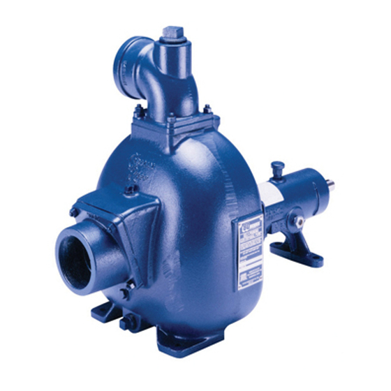
Gorman- Rupp pump. This pump is an 80 Series, semi-open impeller, self- priming centrifugal model with a suction check valve. It is close-coupled to a single cylinder, air Immediate hazards which WILL result in cooled Kohler gasoline engine. - Page 6 80 SERIES OM−03427 SAFETY - SECTION A This information applies to 80 Series en- gine driven pumps. Refer to the manual accompanying the engine before at- This pump is designed to handle most tempting to begin operation. non-volatile, non-flammable liquids containing specified entrained solids.
- Page 7 80 SERIES OM−03427 2. Ventilate the area. fuel lines are securely connected and free of leaks. Never refuel a hot or run- 3. Allow the pump to completely cool. ning engine. Avoid overfilling the fuel 4. Check the temperature before tank.
-
Page 8: Installation − Section B
80 SERIES OM−03427 INSTALLATION − SECTION B Review all SAFETY information in Section A. If installed in a flooded suction application where the liquid is supplied to the pump under pressure, Follow the instructions on all tags, labels and some of the information such as mounting, line decals attached to the pump. -
Page 9: Preinstallation Inspection
OM−03427 80 SERIES OUTLINE DRAWING Figure 2. Pump Model 82E2−M8 S/G PREINSTALLATION INSPECTION maximum shelf life. These must be inspected or replaced to ensure maximum pump serv- ice. The pump assembly was inspected and tested be- fore shipment from the factory. Before installation,... -
Page 10: Positioning Pump
80 SERIES OM−03427 Refer to the information accompanying the battery The pump may have to be supported or shimmed and/or electrolyte solution for activation and charg- to provide for level operation or to eliminate vibra- ing insructions. tion. If the pump has been mounted on a moveable... -
Page 11: Gauges
OM−03427 80 SERIES place by tightening the flange bolts and/or cou- Strainers plings. If a strainer is furnished with the pump, be certain Lines near the pump must be independently sup- to use it; any spherical solids which pass through a... -
Page 12: Suction Lines In Sumps
80 SERIES OM−03427 Suction Lines In Sumps of one or both pumps. To avoid this, position the suction inlets so that they are separated by a dis- If a single suction line is installed in a sump, it tance equal to at least 3 times the diameter of the should be positioned away from the wall of the suction pipe. -
Page 13: Discharge Lines
OM−03427 80 SERIES stalled in the discharge line to protect the pump DISCHARGE LINES from excessive shock pressure and reverse rota- tion when it is stopped. Siphoning Do not terminate the discharge line at a level lower than that of the liquid being pumped unless a si- phon breaker is used in the line. -
Page 14: Operation − Section C
OM−03427 80 SERIES OPERATION − SECTION C Review all information in Safety, Section A. Add liquid to the pump casing when: 1. The pump is being put into service for the Follow the instructions on all tags, labels and first time. -
Page 15: Lines Without A Bypass
OM−03421 80 SERIES line. Air from the suction line will be discharged through the bypass line back to the wet well during the priming cycle. When the pump is fully primed and liquid is flowing steadily from the bypass line, Do not remove plates, covers, gauges, open the discharge throttling valve. -
Page 16: Stopping
OM−03427 80 SERIES Cold Weather Preservation STOPPING Never halt the flow of liquid suddenly. If the liquid being pumped is stopped abruptly, damaging shock waves can be transmitted to the pump and In below freezing conditions, drain the pump to piping system. -
Page 17: Troubleshooting − Section D
80 SERIES OM−03427 TROUBLESHOOTING − SECTION D Review all Safety information in Section A. Before attempting to open or service the pump: 1. Familiarize yourself with this manual. 2. Shut down the engine and discon- nect the spark plug wire to ensure that the pump will remain inopera- tive. - Page 18 OM−03427 80 SERIES TROUBLE POSSIBLE CAUSE PROBABLE REMEDY PUMP STOPS OR Air leak in suction line. Correct leak. FAILS TO DELIVER Lining of suction hose collapsed. Replace suction hose. RATED FLOW OR PRESSURE Leaking or worn seal or pump gasket.
-
Page 19: Preventive Maintenance
80 SERIES OM−03427 equipped) between regularly scheduled inspec- PREVENTIVE MAINTENANCE tions can indicate problems that can be corrected Since pump applications are seldom identical, and before system damage or catastrophic failure oc- pump wear is directly affected by such things as curs. -
Page 20: Pump Maintenance And Repair - Section E
80 SERIES OM−03427 PUMP MAINTENANCE AND REPAIR - SECTION E MAINTENANCE AND REPAIR OF THE WEARING PARTS OF THE PUMP WILL MAINTAIN PEAK OPERATING PERFORMANCE. STANDARD PERFORMANCE FOR PUMP MODELS 82E2−M8 AND 82E2−M8 S/G Based on 70_ F (21_ C) clear water at sea level Contact the Gorman-Rupp Company to verify per- with minimum suction lift. - Page 21 OM−03427 80 SERIES SECTION DRAWING PARTS PAGE Figure 1. Pump Model 82E2−M8 PAGE E − 2 MAINTENANCE & REPAIR...
-
Page 22: Parts Lists
80 SERIES OM−03427 PARTS LIST Pump Model 82E2−M8 (From S/N 945886 up) If your pump serial number is followed by an N", your pump is NOT a standard production model. Contact the Gorman-Rupp Company to verify part numbers. ITEM PART MAT’L... -
Page 23: Pump Model 82E2−M8
OM−03427 80 SERIES SECTION DRAWING Figure 2. Pump Model 82E2−M8 S/G PAGE E − 4 MAINTENANCE & REPAIR... -
Page 24: Pump Model 82E2−M8 S/G
80 SERIES OM−03427 PARTS LIST Pump Model 82E2−M8 S/G ITEM PART NAME PART MAT’L ITEM PART NAME PART MAT’L NUMBER CODE NUMBER CODE PUMP END ASSY 82E2 −−− −T-TYPE LK WASHER BLO5 15991 KOHLER M8 ENGINE 29127−083 −−− −BATTERY BOX... - Page 25 OM−03427 80 SERIES SECTION DRAWING Figure 3. Pump End Assembly 82E2−(M8) PPO and 82E2−(M8 S/G) PPO PAGE E − 6 MAINTENANCE & REPAIR...
- Page 26 80 SERIES OM−03427 PARTS LIST Pump End Assembly 82E2−(M8) PPO and 82E2−(M8 S/G) PPO ITEM PART NAME PART MAT’L ITEM PART NAME PART MAT’L NUMBER CODE NUMBER CODE PUMP CASING 6851C 10010 PIPE PLUG 15079 HEX HD CAPSCREW B0614 15991...
-
Page 27: Pump And Seal Disassembly And Reassembly
80 SERIES OM−03427 PUMP AND SEAL DISASSEMBLY 4. Check the temperature before opening any covers, plates, or AND REASSEMBLY plugs. 5. Close the suction and discharge Review all Safety information in Section A. valves. 6. Vent the pump slowly and cau- Follow the instructions on all tags, label and de- tiously. -
Page 28: Impeller Removal
80 SERIES OM−03427 move the nuts (22) and separate the pump casing the inboard stationary washer, packing ring, sta- and gasket set (13) from the intermediate (15). Re- tionary and rotating seal elements. move the gasket set (13). Tie and tag the gaskets,... - Page 29 80 SERIES OM−03427 Position the intermediate against the engine, install Handle the seal parts with extreme care to prevent the hoisting bail (12) and secure both parts in place damage. Be careful not to contaminate precision using the attaching hardware (16, 17, 18, 19 and finished faces;...
-
Page 30: Impeller Installation And Adjustment
80 SERIES OM−03427 Pump Casing Installation (Figure 3) This seal is not designed for operation at If the wear plate (23) was removed for replace- temperatures above 110_ F (43_C). Do not ment, secure it to the pump casing using the at- use at higher operating temperatures. -
Page 31: Final Pump Assembly
80 SERIES OM−03427 Final Pump Assembly Refer to OPERATION, Section C, before putting the pump back into service. (Figure 1 or 2) LUBRICATION Be sure the pump and engine are securely mounted to the base. Seal Assembly Install the suction and discharge lines and open all valves. - Page 32 For U.S. and International Warranty Information, Please Visit www.grpumps.com/warranty or call: U.S.: 419−755−1280 International: +1−419−755−1352 For Canadian Warranty Information, Please Visit www.grcanada.com/warranty or call: 519−631−2870 THE GORMAN-RUPP COMPANY D MANSFIELD, OHIO GORMAN-RUPP OF CANADA LIMITED ST. THOMAS, ONTARIO, CANADA...
Need help?
Do you have a question about the 80 Series and is the answer not in the manual?
Questions and answers