Axminster Trade Series Manual
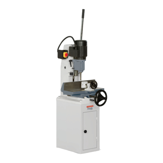
Floor standing morticer
Hide thumbs
Also See for Trade Series:
- Original instructions manual (36 pages) ,
- Manual (32 pages) ,
- Instruction manual (28 pages)
Table of Contents
Advertisement
Quick Links
Advertisement
Table of Contents

Related Manuals for Axminster Trade Series


Summary of Contents for Axminster Trade Series
- Page 1 Code 501208 MT25 Floor Standing Morticer AT&M: 22/04/2014 REF: 508305...
-
Page 2: Declaration Of Conformity
Index of Contents Index of Contents Declaration of Conformity What’s Included General Safety Instructions for 230V Machines 03-04 Specific Safety Instruction for Morticers Specification Unpacking and Assembly 05-06 Illustration and Parts Description 07-08-09 Setting Up the Morticer 10-11-12-13-14 Accessories 15-16 Maintenance 16-17-18-19 Troubleshooting... -
Page 3: What's Included
What’s Included Quantity Item Part Model Number MT25 1 No MT25 Morticer 1 No Operating Lever 1 No Cabinet 2 No 3-4mm Hex Keys 1 No Chuck Key 2 No Bush Adaptors 1.3/16" and 13/16" 1 No Instruction Manual General Safety Instructions for 230V Machines •... -
Page 4: Specification
General Safety Instructions for 230V Machines • Clean machines by wiping with a damp soapy cloth. • Always ensure that long hair is tied back or retained by a Do not use solvents or cleaners that may damage plastic band, hat or safety helmet. Remove all loose jewellery to parts or painted/coated surfaces. -
Page 5: Unpacking And Assembly
Hex screw washer and spring from the rack and pinion assembly and place close to hand, see figs Remove the morticer and stand from the shipping 02-03-04. cartons. Report any shortages or damage to Axminster Fig 02-03-04 Tool Centre Customer Services Department. (03332 406406) Rack and Pinion assembly Please dispose of the packaging responsibly;... - Page 6 Unpacking and Assembly Fig 05 Fig 09 Lever coupling Teeth Fig 06 Teeth Chuck Compartment Open the chuck access door by removing the Hex screw and placing it safely aside. Remove the transport packaging, see fig 10 and wipe the chuck over with a cloth.
-
Page 7: Illustration And Parts Description
Illustration and Parts Description Operating lever Wood chip extraction port Motor Head stock gib strip locking bolt Head stock gib strip adjusting screws Lever coupling Chuck access door Head stock Depth stop plate support column Table clamp Clamp wheel Depth setting bar clamp Depth setting bar Depth stop ring collar... - Page 8 Illustration and Parts Description Chuck (A), Morticer head clamping nut (B) NVR ON/OFF Switch shroud for independent vertical adjustment Depth stop plate (A), Depth ring collar (B) and clamping handle (C). Rack and pinion rise The depth stop plate can be repositioned to give a second specific depth and fall mechanism Rack and pinion drive Lead screw access plate (A)
- Page 9 Illustration and Parts Description Table adjustment screws (A), collar stop bar (B) Collar stop (A) Table adjustment Collar stop block (C) Clamping handle (B) locking nuts (A) The table clamp can be adjusted to Table clamp positioning holes accommodate different sizes of timber Gear engaged to move the table from side to side Gear engaged onto the lead screw to move the table from back to front...
- Page 10 Setting Up the Morticer Initial Setup Setting the Chisel Auger Clearance The old rule of thumb for chisel auger clearance was NOTE: Select the correct bush adaptor (F) for the shank known as “the one penny width” . This was achieved by of the required chisel and introduce it into the underside introducing a penny between the locating shoulder of the of chisel head stock.
- Page 11 Setting Up the Morticer Fig B chisel, position the head stock so that the chisel points or General Notes the auger point are at the depth required, raise the depth stop collar to the underside of the head stock and tighten The mortise will generate a lot of ‘grip’...
- Page 12 Setting Up the Morticer Setting the Chisel Depth WARNING!! DISCONNECT THE MORTICER FROM THE MAINS SUPPLY BEFORE CONTINUING! The chisel depth can be set to give two depth settings the first method is adjusting the setting bar and the second is to adjust the ring collar clamp (B).
- Page 13 Setting Up the Morticer Table Clamp Adjusting the Table The table camp can be adjusted to accommodate The work table can be adjusted from back to front and different sizes of timber using the pre-drilled holes in from left to right by the operating the, main control wheel the table.
- Page 14 Setting Up the Morticer Front to Back Movement Table Distance Stops To the rear of the worktable there are two collar stops Pull the wheel out to engage the drive gear into the lead to set a required distance for repetitive work. screw thus enablining the table to move from front to back, see fi gs 25-26-27.
- Page 15 The Japanese pattern has a point on the joint. This Axminster mortice chisel sharpening kit will fi t end of the bit and one cutting spur and most Taiwanese and Japanese mortice chisels metric and spiral for rapid chip clearance.
-
Page 16: Maintenance
Accessories Machine Moblie Base Code: 708118 Instructions Use the cones in a drill press or your morticer if you have A steel base, adjustable for size, with fixed wheels on the a chuck adaptor (a handheld drill is neither suitable nor back corners and two lockable castoring wheels on the safe). - Page 17 Maintenance Fig 33-34 Fig 35-36 Gib strip screws Locking Hex bolts To ensure optimum performance from your morticer Head Stock Adjustment routine cleaning and lubrication is required. If there is sufficient play happening in the head stock assembly, loosen the three locking Hex bolts (E) to the After long periods of use wood and resin deposits will right side of the head stock column and carefully adjust build up on the table and the rack and pinion gears.
- Page 18 Maintenance General Maintenance Light Lubricate Lubricate...
- Page 19 Bits are best sharpened with a small file and chisels sharpen the inside only, see figs 37-38. with the special mortice chisel sharpeners, see our catalogue or visit our website at axminster.co.uk WARNING!! DO NOT SHARPEN, STONE OR GRIND THE BIT ON THE OUTSIDE WHICH WILL REDUCE...
-
Page 20: Troubleshooting
Troubleshooting Symptom Possible Causes Solutions 1. Fuse blown or circuit breaker Replace fuse or reset circuit breaker Morticer will not start tripped. 2. Cord damaged. Replace the power cord by a qualified electrician. 1. Extension cord too light or too long. 1. - Page 21 Exploded Diagram/List...
- Page 22 Exploded Diagram/List No. Description Pan HD Screw M5×20 Depth Setting Bar Small Handwheel Retaining Ring Setting Screw 6×16 Lead Screw Locating Block Spring Washer M6 Roll Pin 6×26 Hex Socket Head Screw Hex Screw M6×30 M8×40 Base Clamp Hex Socket Head Screw Strip M6×20 Setting Screw M8×12...
-
Page 23: Wiring Diagram
Wiring Diagram... - Page 24 Normal wear and tear; misuse, abuse and neglect are excluded and the machine should not have been engineering machines, Axminster Air compressors and Air Tools, and bench top grinders - no modified in any way. Please do not attempt to service the product without first contacting us; we are registration necessary just proof of purchase.
Need help?
Do you have a question about the Trade Series and is the answer not in the manual?
Questions and answers