Axminster Trade Series Original Instructions Manual
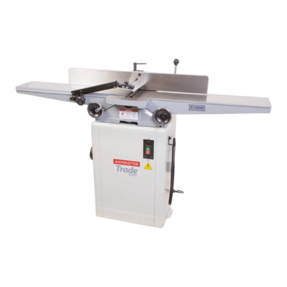
150mm planer
Hide thumbs
Also See for Trade Series:
- Manual (32 pages) ,
- Instruction manual (28 pages) ,
- User manual (20 pages)


Need help?
Do you have a question about the Trade Series and is the answer not in the manual?
Questions and answers