Advertisement
Quick Links
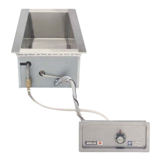
011C
WELLS MANUFACTURING
265 Hobson Street, Smithville, Tennessee 37166
telephone: 314-678-6314
fax: 314-781-2714
www.wells-mfg.com
OWNERS MANUAL
BUILT-IN
MODULAR
AUTO-FILL
WARMERS
MODELS
MOD-100TD/AF
MOD-127TD/AF
Includes
INSTALLATION
USE & CARE
EXPLODED VIEW
PARTS LIST
MOD-100TD/AF
WIRING DIAGRAM
IMPORTANT: DO NOT DISCARD THIS MANUAL
This manual is considered to be part of the appliance and is to be given to the OWNER or
MANAGER of the restaurant, or to the person responsible for TRAINING OPERATORS of
this appliance. Additional manuals are available from your WELLS DEALER.
THIS MANUAL MUST BE READ AND UNDERSTOOD BY ALL PERSONS USING OR
INSTALLING THIS APPLIANCE. Contact your WELLS DEALER if you have any
questions concerning installation, operation or maintenance of this equipment.
2M-308022 Rev. A
03/18
Advertisement

Related Manuals for Wells MOD-100TD/AF


Summary of Contents for Wells MOD-100TD/AF
- Page 1 Additional manuals are available from your WELLS DEALER. THIS MANUAL MUST BE READ AND UNDERSTOOD BY ALL PERSONS USING OR INSTALLING THIS APPLIANCE. Contact your WELLS DEALER if you have any questions concerning installation, operation or maintenance of this equipment.
- Page 2 Wells’ discretion have the parts replaced or codes, including incorrect gas or electrical connection. Wells is not liable repaired by Wells or a Wells-authorized service agency.
- Page 3 PARTS & SERVICE CUSTOMER SERVICE DATA INTRODUCTION Thank You for purchasing this Wells Manufacturing appliance. Proper installation, professional operation and consistent maintenance of this appliance will ensure that it gives you the very best performance and a long, economical service life.
- Page 4 FEATURES & OPERATING CONTROLS A. THERMOSTAT 1. On THERMOSTATICALLY CONTROLLED warmers, power is applied to the heating element according to the control knob position and the actual temperature at the temperature sensing thermobulb. 2. The desired temperature is controlled by rotating the TEMPERATURE CONTROL KNOB.
- Page 5 Do not operate this appliance if the control panel is damaged. Call these instructions are not your Authorized Wells Service Agent for service. followed. The technical content of this manual, including any wiring diagrams, schematics, parts breakdown illustrations and/or adjustment procedures, is intended for use by qualified technical personnel.
- Page 6 INSTALLATION NOTE: DO NOT discard UNPACKING & INSPECTION the carton or other packing Carefully remove the appliance from the carton. Remove all materials until you have protective plastic film, packing materials and accessories from the inspected the appliance for Appliance before connecting electrical power or otherwise performing hidden damage and tested it any installation procedure.
- Page 7 INSTALLATION For “top-mounted” warmers (i.e. warmers mounted from above the counter top): a. Verify that provided sealants are applied to the underside of the warmer top flange prior to setting the unit into the cutout. b. After installation, verify that the tabs on the Wellsloks are turned out to lock the warmer into the counter c.
- Page 8 OPERATION AUTOFILL WARMERS CAUTION: HOT SURFACE 1. Autofill warmers sense water level by a sensor placed at the proper level. For manifolded autofill warmers, the water level Exposed surfaces can be hot sensor / fill tube is in one pan only, normally in the far left pan. to the touch and may cause 2.
- Page 9 Never use metal implements, wire brushes, abrasive scratch pads or steel wool to clean stainless steel. Warmer pans, insets and other vessels are subject to a harsher environment. Wells Manufacturing uses an very high quality stainless steel (#304DDQ) for our food warmer pans.
- Page 10 Contact your Authorized Wells Service Agency to inspect warmer if water or grease contamination is suspected. Close drain valve. Add proper amount of warm water. Turn control...
- Page 11 CLEANING INSTRUCTIONS WEEKLY CLEANING INSTRUCTIONS CAUTION: CHEMICAL BURN PREPARATIONS: Remove any insets, pans and/or adapter tops. HAZARD Drain or remove water from well if used for wet operation. Deilimng chemicals may be caustic. Wear appropriate FREQUENCY: Weekly, or whenever lime or scale is seen personal protective equipment.
- Page 12 One or more pans of an auto-fill Blocked drain manifold Clean drain manifold unit do not fill There are no user-serviceable components in this appliance. In all instances of damage or malfunction, contact your Authorized Wells Service Agency for repairs.
- Page 13 WIRING DIAGRAM...
- Page 14 P2-306960 make from 2H-36050 P2-40843 (150' roll) 2T-45917 P2-Z12587 WS-50131 P2-45066 2C-41974 P2-45067 2J-35687 2I-Z12311 2I-40034 2K-34136 2E-306865 P2-45186 2R-40498 2E-46529 2C-46591 MOD100TDAF/6 P2-46587 2V-70774 (metal body) 100TDAF/6 208 WELLS WELLS (primarily used on Chilis) IL2238, Rev. C MOD100TD/AF COMPONENTS...
- Page 15 2V-47650 2C-30397 2K-47662 make from 2N-300706 2C-46591 2H-36196 (150' roll) P2-300702 THERMOBULB (ref.) D8-303352 2K-34136X 2I-Z12311 2K-31040 P2-306960 P2-45067 P2-40843 2T-45917 P2-48181 WS-50131 2C-41974 2J-35687 2I-Z12311 2K-34136X 2I-40034 2E-306865 2R-40498 2E-46529 2C-46591 P2-46587 WELLS WELLS IL2239, Rev. - MOD127TD/AF COMPONENTS...
- Page 16 NOTES...
- Page 17 NOTES...
- Page 18 PARTS & SERVICE DESCRIPTION PART NO. Always use an inset. DO NOT place food directly ADAPTERS & INSETS into the warmer pan. ADAPTER TOP, convert 12” x 20” warmer to hold two 7 qt. insets WS-21502 ADAPTER TOP, convert 12” x 20” warmer to hold two 4 qt.
- Page 19 1¾” thick WS-22592* contact your Wells authorized service agency, or call: WELLSLOK EXTENSION KIT, for UL LISTED 12” x 20” warmers only, adapt to wood counter Wells Manufacturing up to 1¾”...
- Page 20 WELLS MANUFACTURING 265 Hobson Street, Smithville, Tennessee 37166 telephone: 888-356-5362 fax: 314-781-2714 www.wells-mfg.com...
Need help?
Do you have a question about the MOD-100TD/AF and is the answer not in the manual?
Questions and answers