Table of Contents
Advertisement
Quick Links
MOD100E
MOD100T
IMPORTANT: DO NOT DISCARD THIS MANUAL
This manual is considered to be part of the appliance and is to be given to the OWNER or
MANAGER of the restaurant, or to the person responsible for TRAINING OPERATORS of
this appliance. Additional manuals are available from your WELLS DEALER.
THIS MANUAL MUST BE READ AND UNDERSTOOD BY ALL PERSONS USING OR
INSTALLING THIS APPLIANCE. Contact your WELLS DEALER if you have any
questions concerning installation, operation or maintenance of this equipment.
308017
2M-
Rev. C
WELLS MANUFACTURING
265 Hobson Street, Smithville, Tennessee 37166
telephone: 314-678-6314
fax: 314-781-2714
www.wells-mfg.com
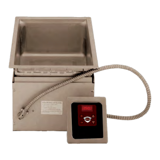
THERMOSTAT & DIGITAL
ELECTRONIC CONTROL
MOD100T, TD, TDWA
OWNERS MANUAL
BUILT-IN
SINGLE WELL
MODULAR
WARMERS
with
MODELS
MOD100E, ED, HE
MOD100HT, HTD
MOD127TD, TDWA
Includes
INSTALLATION
USE & CARE
EXPLODED VIEW
PARTS LIST
WIRING DIAGRAM
011C
03/18
Advertisement
Table of Contents

Subscribe to Our Youtube Channel
Related Manuals for Wells MOD100T


Summary of Contents for Wells MOD100T
- Page 1 Additional manuals are available from your WELLS DEALER. THIS MANUAL MUST BE READ AND UNDERSTOOD BY ALL PERSONS USING OR INSTALLING THIS APPLIANCE. Contact your WELLS DEALER if you have any questions concerning installation, operation or maintenance of this equipment.
- Page 2 Wells’ discretion have the parts replaced or codes, including incorrect gas or electrical connection. Wells is not liable repaired by Wells or a Wells-authorized service agency.
-
Page 3: Table Of Contents
PARTS & SERVICE CUSTOMER SERVICE DATA INTRODUCTION Thank You for purchasing this Wells Manufacturing appliance. Proper installation, professional operation and consistent maintenance of this appliance will ensure that it gives you the very best performance and a long, economical service life. -
Page 4: Features & Operating Controls
FEATURES & OPERATING CONTROLS A. THERMOSTAT On thermostatically controlled warmers, power is applied to the INDICATOR heating element according to the control knob position and the LIGHT actual temperature at the temperature sensing thermobulb. The desired temperature is controlled by rotating the temperature control knob. -
Page 5: Precautions & General Information
Do not operate this appliance if the control panel is damaged. Call installation instructions are your Authorized Wells Service Agent for service. read and followed. Damage to the appliance may result The technical content of this manual, including any wiring diagrams,... -
Page 6: Installation
INSTALLATION NOTE: DO NOT discard UNPACKING & INSPECTION the carton or other packing Carefully remove the appliance from the carton. Remove all protective materials until you have plastic film, packing materials and accessories from the Appliance inspected the appliance for before connecting electrical power or otherwise performing any hidden damage and tested it installation procedure. - Page 7 INSTALLATION 3. For “top-mounted” warmers (i.e. warmers mounted from above the counter top): Verify that provided sealants are applied to the underside of the warmer top flange prior to setting the unit into the cutout. After installation, verify that the tabs on the Wellsloks are turned out to lock the warmer into the counter Apply a thin bead of food-grade silicone sealant around the flange to seal it to the counter.
-
Page 8: Operation
CAUTION: change in wet or dry operation. SHOCK HAZARD Wells Manufacturing recommends operating WET for consistent food heating. DO NOT splash or pour water onto control panel or wiring. If your wet-operation warmer is allowed to run dry, turn it OFF and allow to cool to room temperature before adding water. - Page 9 OPERATION OPERATION Food temperature will vary from Always use an inset. DO NOT place food directly into the warmer. the control set temperature based on the moisture content Check water level in wet-operation warmer frequently during use. and consistency of the food Running warmers dry will lower the temperature of the food in the insert product.
-
Page 10: Maintenance Instructions
Never use metal implements, wire brushes, abrasive scratch pads or steel wool to clean stainless steel. Warmer pans, insets and other vessels are subject to a harsher environment. Wells Manufacturing uses an very high quality stainless steel (#304DDQ) for our food warmer pans. -
Page 11: Cleaning Instructions
Contact your Authorized Wells Service Agency to inspect warmer if water or grease contamination is suspected. Close drain valve. Add proper amount of warm water. Turn control... - Page 12 CLEANING INSTRUCTIONS CAUTION: WEEKLY CLEANING INSTRUCTIONS CHEMICAL BURN PREPARATIONS: Remove any insets, pans and/or adapter tops. HAZARD Drain or remove water from well if used for wet operation. Deilimng chemicals may be caustic. Wear appropriate FREQUENCY: Weekly, or whenever lime or scale is seen personal protective equipment.
-
Page 13: Troubleshooting Suggestions
Drain-equipped unit will not Contact your Authorized Wells Service Agency hold water Drain valve damaged or pan(s) leaking for repairs There are no user-serviceable components in this appliance. In all instances of damage or malfunction, contact your Authorized Wells Service Agency for repairs. - Page 14 EXPLODED VIEW M100T, M100TD, M100HT, M100HTD, & EMOD UNITS THERMOBULB EMOD; Electronic Control See Detail A IL1905, Rev C MODEL: MOD100T, MOD100HT...
- Page 15 Fig No Part No Description Application 2N-300166UL ELEM 208V 1650W MODS MOD100HTD208 ELEM HEATING 208/240V 1650W 2N-303375UL MOD100T, MOD100TD, MOD100T6, MOD100TD6, MOD100HT (Dual Voltage) 2N-46131UL ELEM 120V 1200W M100THTDM-120 2N-46660UL ELEM 240V 1200W LLW-1220 MOD100HTD 2N-46681UL ELEM 120V 1650W SMPT...
- Page 16 EXPLODED VIEW: Detail A M100HE, M100HCE, M100HE6, M100HCE6, M100HED, M100HCED, M100HEAF MOD100HE Nameplate Electronic Control Fab Warmer Nameplate MOD100E Small Profile Electronic Control Fab Warmer IL2513, Rev. -, 8/1/12...
- Page 17 PARTS LIST: Detail A Detail A: EMOD Control Box Assy Fig No Part No Description Application P2-Z14490 CONTROL BOX WELD - SMALL 2C-31053 NUT 8-32 KEPS MS NICKEL 2C-35736 NUT 8-32 HEX KEPS MS GREE 2E-37465 TERM BLOCK 3POLE 85AMP 2C-1496 SCREW 8-32X3/4 RHP STL NP 2C-Z2594...
-
Page 18: Exploded View & Parts List
P2-Z14668 M127CE, E 2C-30397 2N-300706UL P2-300702 2H-36196 (Sold by the foot) D8-303352 THERMOBULB (ref.) P2-45067 P2-Z16805 2I-Z12311 2K-33996X 2T-38968 EMOD; P2-40843 Electronic Control 2J-35687 See Detail A I7-Z12221 2K--31040 2I-Z12311 2R-40498 2K-33996X OF F WELLS WELLS IL2472, Rev. D, 7/15/14... -
Page 19: Wiring Diagram
WIRING DIAGRAM... - Page 20 WIRING DIAGRAM NOTES: WIRING DIAGRAM MOD100E 1) GROUND TO EARTH USING SUPPLIED STUD IN CONTROL BOX. 2) OPTIONAL WATER LEVEL CONTROL: WIRES 19 & 35 SHOULD BE CAPPED IF NOT USED. PROBE ALTERNATE WATER MODEL VOLTS LEVEL CONTROL 1650 1240 1386 1650 MOD100E...
- Page 21 NOTES...
-
Page 22: Parts & Service
PARTS & SERVICE DESCRIPTION PART NO. Always use an inset. DO NOT place food directly into the warmer pan. ADAPTERS & INSETS ADAPTER TOP, convert 12” x 20” warmer to hold two 7 qt. insets WS-21502 ADAPTER TOP, convert 12” x 20” warmer to hold two 4 qt. -
Page 23: Customer Service Data
For factory authorized service, or to order factory authorized WELLSLOK EXTENSION KIT, for UL LISTED replacement parts, contact circular warmers only, adapt to wood counter your Wells authorized service up to 1¾” thick WS-22592* agency, or call: WELLSLOK EXTENSION KIT, for UL LISTED 12”... - Page 24 WELLS MANUFACTURING 265 Hobson Street, Smithville, Tennessee 37166 telephone: 314-678-6314 fax: 314-781-2714 www.wells-mfg.com...
Need help?
Do you have a question about the MOD100T and is the answer not in the manual?
Questions and answers