Table of Contents
Advertisement
Quick Links
Advertisement
Table of Contents

Subscribe to Our Youtube Channel
Related Manuals for Parallel Audio Stage-100 Series


Summary of Contents for Parallel Audio Stage-100 Series
- Page 2 Thank you for purchasing this wireless microphone system. Please take a few moments to read this operating manual to gain a thorough understanding of the function and operation of both transmitter and receiver. In the Box Stage-100 1 Transmitter Pair of Antennas IrDA Receiver (Handheld/Beltpack) Switching Adaptor...
-
Page 3: Front Panel
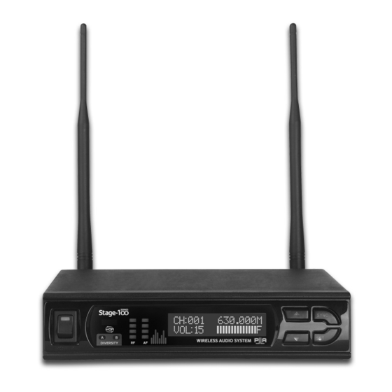
Parts and Functions FRONT PANEL Power switch LCD display IR sensor area UP button Diversity indicator DOWN button Radio frequency indicator IrDA synchronisation button Audio frequency indicator SET button REAR PANEL Antenna B socket (TNC) Balanced audio output Unbalanced audio output DC in Antenna A socket (TNC) OPERATION MANUAL V1.0... -
Page 4: Channel Setting
Channel Setting For an interference- free operation, a cleaner channel might be necessary if the current one receives too much interference. To select a new channel: CHANNEL:001 CHANNEL:010 FREQ:650.000MHz FREQ:652.250MHz Press and release SET button until the CHANNEL | FREQUENCY page appears. Press p(UP) or q(DOWN) button to change the channel number. - Page 5 Channel Synchronising of the Receiver and Transmitter Align infrared areas of the receiver and transmitter within 10~30cm. Sync Channel from Transmitter Ú Receiver Sync Channel from Receiver Ú Transmitter CH:001 CH:001 650.000M VOL:15 IRDA DATA SEND CH:010 PLL CHANNEL VOL:15 COPIED BY IRDA STEP 1: Press the synchronising button of the STEP 1: Press the SYNC button of the receiver.
-
Page 6: Receiver Installation
Adjusting Squelch Level SQUELCH SETUP SQUELCH SETUP LEVEL:01 LEVEL:03 When interference is encountered try reducing the sensitivity of the receiver, thus making it less susceptible to interference. Press and release SET button until the SQUELCH SETUP page appears. Press p(UP) or q(DOWN) button to choose a new level between 1 and 10. 5 seconds after selecting a level, it will be automatically saved. -
Page 7: Audio Output Connection
Audio Output Connection There are two audio outputs on the back of the receiver, Mic-level balanced and Line-level unbalanced. Use shielded audio cable for the connection between the receiver and the amplifier/mixer. If the amplifier/mixer has a 1/4”(6.3mm) phone jack, connect a cable from the 1/4”(6.3mm) unbalanced audio output from the receiver to the amplifier/mixer. - Page 8 UHF HANDHELD MICROPHONE (HH9000) Parts and Functions Cartridge IrDA synchronising button Battery power LED Battery compartment Power switch Colour cap IrDA sensor area Menu button Charging port Setting button Channel Synchronising of the Receiver and Transmitter Align infrared areas of the receiver and transmitter within 10~30cm. Sync Channel from Transmitter Ú...
-
Page 9: Battery Type Setting
Battery Installation and Indicator This microphone requires 2 x AA batteries to operate. To install, remove the battery cover and slide the batteries according to the correct polarity into the battery compartment and replace the battery cover. Note: Batteries contain a corrosive acid that may leak and damage the microphone when stored for a long period. Batteries should be removed from the microphone if it is not to be used for a prolong period of about 4 weeks or more. - Page 10 UHF BELTPACK TRANSMITTER (BP9000) Parts and Functions Antenna Low-impedance gain control (MT) Battery compartment Cover release button Audio mute switch Power switch Battery power LED IrDA synchronising button IrDA sensor area Menu button Mini XLR connector Setting button Charging contacts High-impedance gain control (GT) Channel Synchronising of the Receiver and Transmitter Align infrared areas of the receiver and transmitter within 10~30cm.
- Page 11 Gain Setting (GT/MT) Gain control enables the user to set different output levels. GT (8) is for the use of instrument with high impedance, such as guitar while MT (9) is for the use of low impedance such as lapel or headset microphones. Battery Installation and Indicator This transmitter requires 2 x AA batteries to operate.
- Page 12 * All Parallel Audio products come with a 5 year warranty term, excluding Parallel Audio batteries and CD players (see below). Parallel Audio Limited Battery and CD Player Warranty: Batteries and CD players fitted to all Parallel Audio portable PA products carry a 3 months warranty.
Need help?
Do you have a question about the Stage-100 Series and is the answer not in the manual?
Questions and answers