Table of Contents
Advertisement
Quick Links
Advertisement
Table of Contents

Related Manuals for Omron D6T Series


Summary of Contents for Omron D6T Series
- Page 1 MEMS Thermal Sensors User’s Manual MEMS Thermal Sensors A284-E1-03...
-
Page 2: Table Of Contents
Table of Contents Overview ..........................2 Structure (Part Configuration) ....................2 External Dimensions ........................ 2 Principles of Operation ......................2 Product Features ........................3 Usage Procedure ........................5 Connectors ........................5 Example Electrical Connections ..................6 I2C Specifications ......................8 Example Temperature Value Retrieval Program ............. -
Page 3: Overview
Reference this document together with the product catalog when using this device. Structure (Part Configuration) The D6T series of MEMS Thermal Sensors consists of a small circuit board onto which a silicon lens, thermopile sensor, specialized analog circuit, and logic circuit for conversion to a digital temperature value are arranged. -
Page 4: Product Features
Product Features MEMS Thermal Sensors measure the surface temperature of objects. The D6T-44L-06 model features 16 channels in a 4 x 4 arrangement. The D6T-8L-09 features a single 8-channel array. The D6T-1A-01/-02 models feature a 1-channel sensor chip. The module has been optimized by placing the specialized downstream processing circuit adjacent to the sensor chip to achieve low-noise temperature measurements. - Page 5 The sensitive areas of elements are wider than the FOV-specification width. If the size of the measured object is smaller than the sensitive area of an element, the background temperature of objects other than the intended object will become a factor. Our Thermal Sensors use a reference heat source (a blackbody furnace) to correct temperature values.
-
Page 6: Usage Procedure
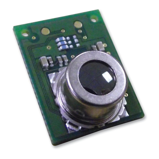
Usage Procedure Connectors Fig. 6. Product Exterior (Reference) Connector Pins Table 1. Connector Pin Table 1 GND GND power supply pin 2 VCC VCC power supply pin (5 V ±10%) 3 SDA I2C (5 V) data 4 SCL I2C (5 V) clock Connector Parts Materials Connector part model: SM04B-GHS-TB (JST) Contact:... -
Page 7: Example Electrical Connections
Example Electrical Connections Scenario 1: 5 V MCU Direct Connection (Same voltage as the microcontroller power supply) Power circuit VDD5 Fig. 7. Connecting to 5 V Microcontroller Scenario 2: 3 V MCU (I2C port is 5 V fault tolerant) Fig. 8. 5 V Fault Tolerant Specification Scenario 3: Using an I2C Level Converter (Not a 5 V fault tolerant specification, or other devices are also connected to the 3 V I2C bus) - Page 8 Scenario 4: Using a Bidirectional Open-Drain GPIO Terminal and Performing I2C Communication Processing in Software (MCU does not have built-in I2C functionality) * Note: Clock stretch support is required (refer to section 6.6). OpenDrain OpenDrain Fig. 10. Using a GPIO Terminal Scenario 5: Using an I2C Bus-Switching IC (Connecting multiple D6T sensors) (This sensor cannot change slave addresses) * Most bus-switching ICs also have power voltage conversion functionality.
-
Page 9: I2C Specifications
Pull-up Resistance Values Values will be adjusted per user calculations of specific usage conditions such as wiring capacitance. (Check the I2C specifications. In most cases, the range is set to approximately 3 k to 10 kΩ.) I2C Specifications Refer to the following table for information on communication specifications Table 2. - Page 10 Fig. 14. I2C Data Line Flow (D6T-1A-01/D6T-1A-02(1ch)) Address Command Repeat Address PTAT PTAT Start W (4Dh) Srart (Lo) (Hi) (Lo) (Hi) P1 to P1021 P1022 P1022 P1023 P1023 Stop (Lo,Hi) (Lo) (Hi) (Lo) (Hi) Output data : 2051 bytes Fig. 15. I2C Data Line Flow (D6T-32L-01A(1024ch)) Note: The command is 4Dh for the D6T-32L-01A only.
- Page 11 Table 3. Content of Received Data (Output Data) PTAT Reference temperature data stored in the sensor The PTAT and Pn temperature data represents values equal to temperature values (°C) multiplied by a factor of 10 as signed 16-bit integers Bit D15 is the sign bit. 25.0°C = 250 (High-byte data = 0x00, Low-byte data = 0xFA) -25.0°C = -250 (High-byte data = 0xFF, Low-byte data = 0x06) P0 to P15...
- Page 12 Signal Chart (The D6T-1A-01/-02 models lack P1 through P15) Fig. 16. Signal Terminal Flow (D6T-1A-01/-02/44L-06) “S” : Start Condition “Sr” : Repeat Start Condition “P” : Stop Condition “W/R” : Write (Lo) / Read (Hi) “ACK” : Acknowledge reply “NACK” : No-acknowledge reply * Refer to the I2C bus specifications for the definitions of these I2C terms.
- Page 13 Before performing the processing illustrated in Fig. 16, perform the following processing for D6T-8L-09 models at least 20 msec after power is supplied to the module. This processing should only be performed when power is first turned on. Command[7:0](0x02) Command[7:0](0x00) Slave address[6:0] (0x0A) Command[7:0](0x01) Command[7:0](0xEE)
- Page 14 Command[7:0] (0x4D) slave address[6:0] (0x0A) slave address[6:0] (0x0A) PTAT Low Byte[7:0] PTAT High Byte[15:8] P0 Low Byte[7:0] P0 High Byte[15:8] PEC data[7:0] P1023 Low Byte[7:0] P1023 Hign Byte[7:0] NACK Fig. 18. Signal Terminal Flow (D6T-32L-01) Fig. 19. Start/Stop Conditions On the D6T-32L-01A, the settings in Table 4 can be changed. Before performing the processing in Fig.
-
Page 15: Example Temperature Value Retrieval Program
Example Temperature Value Retrieval Program (16-channel D6T-44L-06 / 1024ch D6T-32L-01A) / / I 2 C c o m m u n i c a t i o n f u n c t i o n s e x t e r n v o i d I 2 C _ s t a r t ( ) ;... - Page 16 Example Temperature Values (PTAT, P0, P1, …, P15, and PEC in order from the left) 223 ,224,224,273,335,239,221,240,297 ,264,232,221,254,299,258,229,233 ,80 223 ,271,261,265,304,284,270,264,274 ,302,285,271,260,319,304,286,269 ,193 223 ,296,273,285,311,306,291,281,301 ,311,310,293,296,312,322,311,302 ,83 PTAT = 22.3°C, P0 = 29.6°C, P1 = 27.3°C, P2 = 28.5°C, P3 = 31.1°C, etc. * With this example temperature program, only one set of measurements are retrieved.
- Page 17 (Added sections for the 8-channel D6T-8L-09) i n t D 6 T _ g e t v a l u e ( ) I 2 C _ s t a r t ( ) ; I 2 C _ s e n d ( 0 x 1 4 , 0 x 0 2 , 0 x 0 0 , 0 x 0 1 , 0 x E E ) ; I 2 C _ s t o p ( ) ;...
-
Page 18: Example Pec Check Routine
Example PEC Check Routine PEC represents CRC-8 error check data. This data is appended to the end of communication output. The user can use the PEC value to detect communication errors and improve data reliability. (Refer to SMBus specifications for more information) unsigned char calc_crc( unsigned char data ) int index;... -
Page 19: Clock Stretch (Wait)
Clock Stretch (Wait) This slave (sensor) can generate a signal sent to the master (MCU) to tell the MCU to wait before sending a request, in accordance with the temperature data state. The master must support this wait processing. The built-in I2C module in most MCUs has automatic support for this feature. -
Page 20: Communication Timeouts
Communication Timeouts This sensor determines that a timeout has occurred and stops communication if low input continues to be received on the SDA or SCL terminal for the following times. · D6T-44L-06 : 1 sec · D6T-1A-01/D6T-1A-02/D6T-8L-09 : 70 msec When the sensor determines that a communication timeout has occurred, a NACK is returned during a Write access operation. -
Page 21: Sensor Securement
Sensor Securement Install the MEMS Thermal Sensor so that it is enclosed by casing and secured at mountable areas. D6T-44L-06 D6T-8L-09 D6T1A-01 / -02 D6T-32L-01A Fig. 24. Mountable Areas (Shaded Areas) Fig. 25. Sensor Securement (Reference) D6T MEMS Thermal Sensors User’s Manual (A284) -
Page 22: Faq
5 to 6 m. Question Can power consumption be reduced further? Answer The D6T series of sensors is not configured with a "operation mode for power-conserving sleep". As such, the power to the sensor must be shut off to reduce power consumption. Question... -
Page 23: Definition Of Terms
Definition of Terms Thermopile A device cascaded to a thermocouple to increase voltage. Thermocouples are arranged so that hot junctions are adjacent. NETD (used in catalogs) Acronym for Noise Equivalent Temperature Difference. This represents the conversion of noise into a temperature value. - Page 24 Electronic and Mechanical Components Company Regional Contact Americas Europe https://www.components.omron.com/ http://components.omron.eu/ Asia-Pacific China https://ecb.omron.com.sg/ https://www.ecb.omron.com.cn/ Korea Japan https://www.omron-ecb.co.kr/ https://www.omron.co.jp/ecb/ © OMRON Corporation 2018-2019 All Rights Reserved. Cat. No. A284-E1-03 In the interest of product improvement, specifications are subject to change without notice. 1019 (0718)(O)
Need help?
Do you have a question about the D6T Series and is the answer not in the manual?
Questions and answers