
Subscribe to Our Youtube Channel
Related Manuals for Chromalox CXH-C-03S


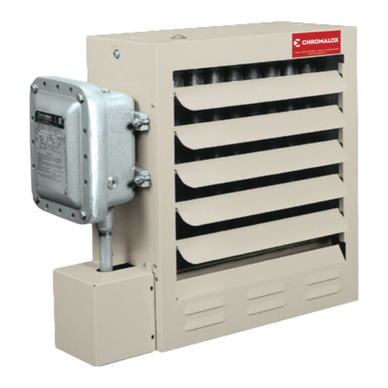
Summary of Contents for Chromalox CXH-C-03S
- Page 1 Installation and Operation Instructions CXH CE AM Forced-Air Heater CXH Series Heaters for Hazardous Locations 0359 II 2 G EEx d IIB T3 ITS02ATEX1048/8 PF490 CE AM 161-302421-006 March 2016...
- Page 2 Mounting Hole mm (In.) Locations mm Horiz. Air (In.) Discharge Model Voltage and Phase m (ft.) BTUH /hr) (Lbs.) CXH-C-03S 380/400/415V 3ph 50Hz 208/240V-1 or 10,236 485.8 606.4 533.4 88.9 346.1 3ph 60Hz 480/575V 3ph 60Hz (8.5) (1189) (127) (19-1/8)
- Page 3 A material safety data 14. Do not install any type of gasket material on any of the sheet (MSDS) is available from Chromalox upon request. electrical junction box cover surfaces. Should leakage occur, remove unit from service and in- vestigate cause.
-
Page 4: General Information
FIRE/EXPLOSION HAZARD. Mount only in upright po- sition and observe nameplate mounting clearances. If using mounting hardware or a supporting structure not supplied by Chromalox, the unit should be suspended from Heater Location instructions: the supporting structure thru the two mounting points on Arrange units so their discharge air streams: top of the unit with 5/8 NC bolts and lockwashers. -
Page 5: Installation Clearances
(4 ft) in front of heater for air stream to discharge freely. pole mounted. One of the Chromalox mounting kits shown in Figures 5, 6 and 7 must be used whenever possible. -
Page 6: Electrical Components
Wall Mount Kit Pole or Wall Mount Kit Model # WMB-12 12” Fan (3-10 kW) Model # PMB-12 12” Fan (3-10 kW) Model # WMB-16 16” Fan (15-20 kW) Model # PMB-16 16” Fan (15-20 kW) Model # WMB-20 20” Fan (25-35 kW) Model # PMB-20 20”... - Page 7 Model kW Ph Volts Size (ga) Amps. Amps. Dia. could result in personal injury or property damage. CXH-C-03S 16.9 Heater must be installed by a qualified person in ac- CXH-C-03S cordance with the National Electrical Code, NFPA 70. CXH-C-03S 14.6...
- Page 8 7. Installation must include appropriate over current protec- supplied). If normal airflow is restricted, or stopped, the tion devices (fusing or circuit breakers) as required by ap- unit will be cycled off by the high temperature cutout. The plicable electric codes in the supply line to the unit. Refer high temperature cutout is also designed to shut down to nameplate for proper current ratings.
- Page 9 Transformer Color Code Tabulation PRI. XFMR 120V SEC 24V SEC Refer to Nameplate VOLT. LEAD CLRS. LEAD CLRS. LEAD CLRS. for Input Voltage Optional – – Disconnet – – Switch BLK/RED 575/600 Optional Aux. Cont. Primary Control Transformer Refer to Nameplate for Primary (Input) and Secondary (Control) Voltage.
- Page 10 Transformer Color Code Tabulation PRI. XFMR 120V SEC 24V SEC Refer to Nameplate VOLT. LEAD CLRS. LEAD CLRS. LEAD CLRS. for Input Voltage – – Optional Disconnet – – Switch BLK/RED 575/600 Primary Control Transformer Refer to Nameplate for Primary (Input) Optional Aux.
-
Page 11: Model Number Description
Refer to Nameplate Transformer Color Code Tabulation for Input Voltage PRI. XFMR 120V SEC 24V SEC VOLT. LEAD CLRS. LEAD CLRS. LEAD CLRS. L2 L3 Optional Disconnet Switch – – – – BLK BLK/RED 575/600 Optional Aux. Cont. Primary Control Transformer Refer to Nameplate for Primary (Input) and Secondary (Control) Voltage. -
Page 12: Operation
Operation 2. The finned structure of the heat exchanger must be kept clean and free of accumulated dust and dirt. The cabi- net front panel is easily removed providing access to the EXPLOSION HAZARD. Heater should not be operated heater core for periodic cleaning. in ambient temperature higher than 40°C (104°F) or in atmospheres corrosive to the heater itself. - Page 13 Maintenance and Repair The occurrence of the manual reset limit control to trip is an abnormal condition. Care should be taken to determine the exact reason that the high limit control tripped before a man- ual reset of the limit control. Possible problem areas could be dirty heat exchanger, blocked air inlet or outlet, fan/motor malfunction, too high operating ambient, incorrect operating voltage, or leaking heat exchanger.
- Page 14 3. Removal of fan blade does not require that the motor When provided, the following components are located in the wiring be disturbed. To clean, service or change the fan cast aluminum hazardous location enclosure. Remove cover blade proceed as follows: and retaining bolts to gain access the following items (See Figure 15): A.
- Page 15 Renewal Parts Identification Publication Number Title PF458 Mounting Kits for Model CXH-EP PF461 Material Safety Data Sheet Chromakool EG PF462 Material Safety Data Sheet Chromakool PG Electrical Control Voltage 24 V 120 V 230 V Contactor 072-304551-002 072-304551-008 072-52560-011 Aux Contactor 072-304551-103 072-304551-103 –...
- Page 16 Figure 16...
-
Page 17: Common Parts
Shown in Figure 16 Motor & Heat Exchanger Parts Code CXHA-03, CXH-A-15, CXH-A-25, Model Heat Exchanger* Item 49 05, 07 & 10 18 & 20 30 & 35 CXH-C-03S-81 353-305234-001 Item# Description Part No. Part No. Part No. CXH-C-03S-83 353-305234-001 Panel wrapper... - Page 18 Limited Warranty: Please refer to the Chromalox limited warranty applicable to this product at http://www.chromalox.com/customer-service/policies/termsofsale.aspx. Chromalox 103 Gamma Drive Pittsburgh, PA 15238 (412) 967-3800 www.chromalox.com © 2016 Chromalox, Inc. All rights reserved.
Need help?
Do you have a question about the CXH-C-03S and is the answer not in the manual?
Questions and answers