Table of Contents
Advertisement
Quick Links
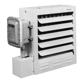
RENEWAL PARTS IDENTIFICATION
Forced Air Heater
for Hazardous Locations
Class I - Groups C & D, Div. 1 & 2
Table A – Specifications
Model
CXH-A-03
CXH-A-05
CXH-A-07
CXH-A-10
CXH-A-15
CXH-A-18
CXH-A-20
CXH-A-25
CXH-A-30
CXH-A-35
© 2010 Chromalox, Inc.
Chromalox
Installation Instructions
and
CXH-A-03 EP to CXH-A-35 EP
Class II - Groups E, F & G
T3B - 165˚C (329˚F)
Horiz. Air
Discharge
kW
Voltage and Phase
208/240V-1 or 3Ø
3
480/575V-3Ø
208/240V-1 or 3Ø
5
480/575V-3Ø
208/240V-1 or 3Ø
7.5
480/575V-3Ø
240V-1 or 3Ø
10
208/480/575V-3Ø
208/240/480V
15
575V-3Ø
18
240V-3Ø
20
480/575V-3Ø
25
480/575V-3Ø
30
480/575V-3Ø
35
480/575V-3Ø
®
(Ft.)
BTUH
CFM
28
10,236
700
28
17,060
700
32
25,590
840
32
34,120
840
47
51,180
1450
43
61,420
1400
43
68,240
1400
54
85,300
2330
54
102,360
2330
54
119,420
2330
SERVICE REFERENCE
4
DIVISION
SALES
(Supersedes PF490-4)
REFERENCE
JULY, 2004
DATE
2"
B
D
A
11-1/16"
C
Overall Dimensions
(In.)
Wt.
(Lbs.)
A
B
127
19-1/8
23-7/8
127
19-1/8
23-7/8
133
19-1/8
23-7/8
138
19-1/8
23-7/8
150
25
27-7/8
165
25
27-7/8
165
25
27-7/8
200
32-1/8
31-7/8
200
32-1/8
31-7/8
200
32-1/8
31-7/8
CXH-A
SECTION
PF490-5
161-302421-004
2"
E
A
5/8" UNC Tapped
Mounting Hole
Locations
C
D
E
21
3-1/2
13-5/8
21
3-1/2
13-5/8
21
3-1/2
13-5/8
21
3-1/2
13-5/8
21
4-13/32
17-5/8
21
4-13/32
17-5/8
21
4-13/32
17-5/8
21-3/4
5-1/2
21-5/8
21-3/4
5-1/2
21-5/8
21-3/4
5-1/2
21-5/8
Advertisement
Table of Contents

Subscribe to Our Youtube Channel
Related Manuals for Chromalox PF490-5


Summary of Contents for Chromalox PF490-5
-
Page 1: Installation Instructions
208/240V-1 or 3Ø CXH-A-07 480/575V-3Ø 240V-1 or 3Ø CXH-A-10 208/480/575V-3Ø 208/240/480V CXH-A-15 CXH-A-18 CXH-A-20 480/575V-3Ø CXH-A-25 480/575V-3Ø CXH-A-30 480/575V-3Ø CXH-A-35 480/575V-3Ø © 2010 Chromalox, Inc. ® Horiz. Air Discharge (Ft.) BTUH 10,236 17,060 25,590 34,120 51,180 1450 575V-3Ø 240V-3Ø 61,420 1400 68,240... - Page 2 4. Heat exchanger contains Propylene Glycol under pressure at oper- ating temperature. A material safety data sheet (MSDS) is avail- able from Chromalox upon request. Should leakage occur, remove unit from service and investigate cause. 5. Keep all electrical enclosure covers tightly closed and secured with all bolts and threads.
-
Page 3: Installation
If using mounting hardware or a supporting structure not supplied by Chromalox, the unit should be suspended from the supporting structure thru the two mounting points on top of the unit with 5/8 NC bolts and lockwashers. If single point mounting is desired, order the correct size Chromalox adapter bracket (P/N 027-302361-001 for 12”... -
Page 4: Mounting Kits
Wall Mount Kit Model # WMB-12 12” Fan (3-10 kW) Model # WMB-16 16” Fan (15-20 kW) Model # WMB-20 20” Fan (25-35 kW) 12” Fan - 16-3/4” 16” Fan - 18-1/2” 1”ø Hardware % Bolt 20” Fan - 22” Single Point Wall Swivel Mount... - Page 5 ELECTRIC SHOCK HAZARD. Disconnect all power before installing or servicing heater. Failure to do so could result in personal injury or property damage. Heater must be installed by a qualified person in accor- dance with the National Electrical Code, NFPA 70. ELECTRIC SHOCK HAZARD.
-
Page 6: Wiring Diagrams
DIAGRAM I Refer to Name Plate for Input Voltage L1 L2 Optional Disconnect Switch Refer to Nameplate for Transformer Voltage Built in or External Thermostat DIAGRAM II Refer to Name Plate for Input Voltage L1 L2 L3 Optional Disconnect Switch Refer to Nameplate for Transformer Voltage... -
Page 7: Model Number Description
CXH-A Heater Voltage 2 = 240V 6 = 575V 3 = 380V 8 = 208V 4 = 480V 9 = 600V 5 = 415V Heating Element Rating 03 = 3.0 kW 18 = 18.0 kW 05 = 5.0 kW 20 = 20.0 kW 07 = 7.5 kW 25 = 25.0 kW 10 = 10.0 kW 30 = 30.0 kW... - Page 8 The occurrence of the manual reset limit control to trip is an abnormal condition. Care should be taken to determine the exact reason that the high limit control tripped. Possible problem areas could be dirty heat exchanger, blocked air inlet or outlet, fan/motor malfunction, too high operating ambient, incorrect operating voltage, or leaking heat exchanger.
-
Page 9: Control Transformer
1. CONTROL TRANSFORMER This item is located in the electrical enclosure. It may be replaced while in the enclosure. To service or replace remove the quick connect wires and mark their locations. Remove two screws which hold the transformer in place. Note transformer orientation and voltage labels on top. - Page 10 RENEWAL PARTS IDENTIFICATION Electrical Control Voltage Contactor 072-304551-002 Transformer 208/240/480 PRI 315-304252-002 Transformer 575 PRI 315-304252-005 Aux. Contactor 072-304551-102 Transformer 380/415 PRI 315-304252-006 Transformer CXH-B — Figure 16 Figure 17 120V 072-304551-008 315-304252-001 315-304252-003 072-304551-102 315-304252-007 315-304252-008 Transformer Contactor...
- Page 11 MANUFACTURER PART NUMBER BREAKDOWN Common Parts Code CXH-A-03 05, 07&10 Item# Description Part No. Panel wrapper 207-303891-001 Panel Bottom 207-303881-001 Panel Front 207-303883-001 Louver 182-303884-001 Washer Shoulder 328-302074-002 Spring 276-130368-001 Terminal Box Cover 080-302079-001 Screw 10-32 248-073662-002 Fan Blade Consult Factory Fan Guard 134-302063-004 Enclosure...
- Page 12 Limited Warranty: Please refer to the Chromalox limited warranty applicable to this product at http://www.chromalox.com/customer-service/policies/termsofsale.aspx. 2150 N. RULON WHITE BLVD., OGDEN, UT 84404 Phone: 1-800-368-2493 www.chromalox.com...
Need help?
Do you have a question about the PF490-5 and is the answer not in the manual?
Questions and answers