
Related Manuals for Chromalox HVH Series


Summary of Contents for Chromalox HVH Series
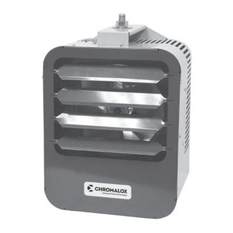
- Page 1 Installation Instructions Type HVH Horizontal/Vertical Unit Heater PF505-10 161-305679-001 May 2019...
- Page 3 HVH Horizontal/Vertical Unit Heater General Heater Location Instructions: Large rooms require multi-unit installation. Number and capacity of units will be determined by volume of build- Arrange units so their discharge air streams: ing and square feet of floor area to be heated. Arrange A.
- Page 4 The wall or mounting surface, and the anchoring pro- Table B – Weights of Heater & Bracket visions must be capable of supporting the combined WEIGHT (Lbs.) weight of the heater and mounting brackets cantilevered Heater and Brackets from the mounting surface. (Refer to Table B for weights Wall Ceiling of heater and brackets and for cantilevered force ex-...
-
Page 5: Installation
Installation NOTICE – These heaters are designed for wall and ceiling mount. Other modes of mounting void factory warranty. Vertical Air Flow 1. Height above floor A. It is recommended that the heater only be used with ceiling heights of 12 feet or greater. Minimum spacing to ceiling is 6 inches, use 3/8-18”... - Page 6 CEILING – Horizontal Airflow (See Figure 5): require to install bracket to heater only. Complete in- The ceiling mounting bracket is fastened to the top stallation requires additional bolts (not supplied) to se- of the heater using the four (4) bolts supplied with the cure to wall.
- Page 7 Dimensions (in.) Bracket Bracket Model No. Wt. (Lbs.) Use With HVW1 16-1/16 18-7/8 17-5/8 3-3/4 HVH-02, 04, 05 HVW2 16-1/16 23-1/4 18-5/8 6-1/2 HVH-07, 10, 12, 15 HVH-02 to 15 (Note 1) 4-15/16 20-1/16 HVW3 23-7/16 6-7/8 HVH-20 HVW4 32-13/16 10-3/8 HVH-25, 30, 35, 40, 45, 50 8-1/2...
-
Page 8: Power Disconnect Switch
POWER DISCONNECT SWITCH (Available as a kit or factory installed option). This switch disconnects the power to the power leads when ELECTRIC SHOCK HAZARD. Be sure electricity is the handle is turned to its off position. Refer to Instruc- turned off at main switch first before wiring. Any tion Sheet PF207. - Page 9 REMOTE FAN SWITCH CONTROL VOLTAGE WIRING — EXTERNAL RE- MOTE THERMOSTATS AND FAN SWITCHES 480V + Heaters require an additional fan relay. (Avail- able as a kit or factory installed option and standard on heaters 20kW and above). The wall switch is packed in the wiring compartment. ELECTRIC SHOCK HAZARD.
- Page 10 See Note #2 Optional thermostat built-in or field installed Optional Motor 3Ø Wiring thermostat Motor built-in or 3Ø Wiring field installed TO T1 TO T1 TO T2 TO T1 TO T3 TO T1 TO T3 TO T2 TO T2 TO T3 TO T3 Yellow TO T2...
- Page 11 Capacitor Elements 3 Phase Wiring Fusing Alternate 1PH Motor Wiring Optional Pliot Light Built In or Remote Fusing Thermostat Termnal Block (Control) AR Cutout Motor Contactor Time Delay Relay Refer to Nameplate for Transformer XFMR Primary Line 40VA Line (Input) and Fusing Fusing Seconday...
-
Page 12: Maintenance And Troubleshooting
Operating Integral Disconnect Switch 1. Chromalox HVH models equipped with an integral disconnect allow for power to be locally isolated from the heater. 2. The disconnect switch used on HVH models is a rotary style disconnect, designed for easy on/off operation. -
Page 13: Troubleshooting
Troubleshooting Problem Probable Cause Solution Unit will not turn on Turn dial in clockwise direction to increase tem- Thermostat set point too low. perature set point. Check control and power circuit to make sure Improper or loose wire they are wired properly and for any loose wire connections. - Page 14 Al- ways specify voltage, phase and kW by listing them on the purchase order specifications. Limited Warranty: Please refer to the Chromalox limited warranty applicable to this product at http://www.chromalox.com/customer-service/policies/termsofsale.aspx. Chromalox, Inc.
Need help?
Do you have a question about the HVH Series and is the answer not in the manual?
Questions and answers