
Related Manuals for Chromalox DH


Summary of Contents for Chromalox DH
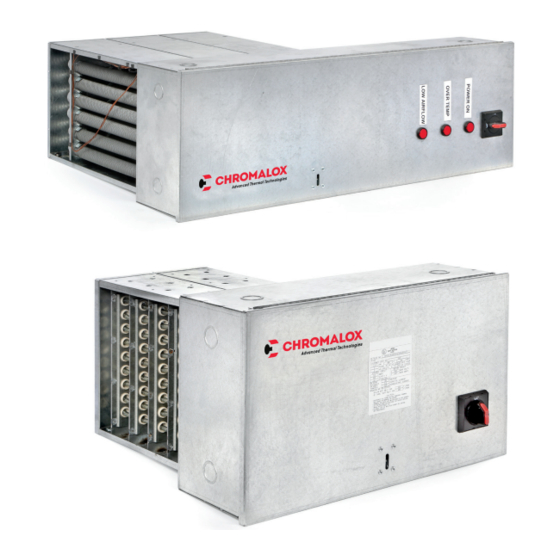
- Page 1 Installation Instructions DH and DHOC Electric Duct Heaters PF503 161-562766-001 February 2015...
-
Page 2: Table Of Contents
Table of Contents Section Page General ..........................3 Installation ..........................3 Mounting ..........................6 Wiring ..........................10 Operation .........................11 Maintenance ........................11 Heater Bundle Removal and Replacement ..............11 Replacement Parts ......................12 Troubleshooting .......................13... -
Page 3: General
DH and DHOC Electric Duct Heaters General Read and understand all instructions before in- FIRE/EXPLOSION HAZARD. This heater is not stalling, servicing or operating product. Failure intended for use in hazardous atmospheres to do so could result in personal injury or prop- where flammable vapors, gases, liquids or erty damage. - Page 4 2. Installation near air handler discharge. (Refer to Fig. 2). 5. Installation with duct transitions in some air distri- bution systems, the duct heater may be consid- Duct Heater erably larger than the ductwork and the duct area must be increased by a sheet metal transition. The slope of the transformation piece on the upstream side of the equipment is limited to 30°...
- Page 5 Flexible Duct Inner Baffle Insert Type Perforated Metal (Must be suitable Duct Heater (50% Open Area) for 195°F) Duct Heater 4 Ft. Min. Figure 8 Remove Bracket and 10. Installation with dampers or filters. Maintain at least Oversized Duct Use Sheetmetal Screws 4’...
-
Page 6: Mounting
Air Flow Flow through duct heater must never drop below the or slightly up stream from the heater after installation. minimum air velocity shown on duct heater nameplate. (Refer to Figure 10). Large ducts will require additional If the air handling system includes filters, they must be readings taken at locations in addition to the centerline. - Page 7 Figure 12 Airflow Right Airflow Airflow Right Left Airflow Left Horizontal duct with panel extended Horizontal duct with panel in RIGHT direction extended in left direction Airflow Airflow Airflow Down Airflow Down Vertical duct with panel extended Vertical duct with panel extended in Upward direction in DOWNWARD direction Airflow...
- Page 8 (H in figure 14) and a standard depth (D in figure 14). If the frame does not match the specified dimensions contact a Control Chromalox representative. Sheet Metal 1. Measure the height and width of the heater frame Screws and note (H and D per figure 14).
- Page 9 16) and a standard depth (D in figure 16). If the frame does not match the specified dimensions contact a Chromalox representative. 1. Measure the height and width of the heater frame and note (H and D per figure 16).
-
Page 10: Wiring
Wiring 4. Connect field wiring to the Duct Heater using the Wiring Diagram provided with the heater. ELECTRIC SHOCK HAZARD. Disconnect all 5. Conduit attachment to heater: power before installing or servicing heater. a. Ensure that conduit size used matches the Failure to do so could result in personal injury knock-out size(s) provided on Duct Heater or property damage. -
Page 11: Operation
Operating Instructions Heater Start-up: Heater Shut-Down: 1. Close the duct heater’s door and ensure that the 1. With the blower or fan still running, turn the Selector latch has engaged by pulling on the door. The door handle on the duct heater to the “OFF” position. should not open unless a tool is used to disengage 2. -
Page 12: Replacement Parts
2. Remove wiring from terminal pins of heater bank. 4. Remove screws around the outside of the heating bank that hold the heating bank to the housing. 3. Remove thermal cutouts if they are attached to the bank that needs to be replaced. Replacement Parts Description Part Number... -
Page 13: Troubleshooting
Duct Heater Troubleshooting Guide Problem Causes Solution Won’t Power On Field power wires not Connect wires per the Wiring section of the Installation & Operat- (no heat) connected properly ing Manual (IOM) Fuse(s) have blown or Check resistance of fuses using a Multimeter to ensure continuity. breaker has tripped Replace any blown fuses. - Page 14 Replace pilot light don’t turn on Loose Wiring Connection Check wire connections on all control circuit terminations. Limited Warranty: Please refer to the Chromalox limited warranty applicable to this product at http://www.chromalox.com/customer-service/policies/termsofsale.aspx. Chromalox, Inc. 2150 N. Rulon White Blvd. Odgen, UT 84404 1-800-368-2493 www.chromalox.com...
Need help?
Do you have a question about the DH and is the answer not in the manual?
Questions and answers