Chromalox CXHA-03 Installation And Operation Instructions Manual
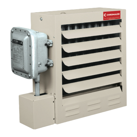
Cxh-a forced-air heater
Hide thumbs
Also See for CXHA-03:

Related Manuals for Chromalox CXHA-03


Summary of Contents for Chromalox CXHA-03
-
Page 1: Installation And Operation
Installation and Operation Instructions CXH-A Forced-Air Heater CXH-A-03 EP to CXH-A-35 EP Class I - Groups C & D, Div. 1 & 2 Class II - Groups E, F & G T3B - 165˚C (329˚F) PF490-11 161-302421-004 June 2018... - Page 2 Table A - Specifications 5/8” UNC Tapped Overall Dimensions (In.) Mounting Hole Locations Horiz. Air Voltage and Discharge Model Phase (ft.) BTUH (Lbs.) CXHA-03 208/240V-1 or 3Ø 10,236 19-1/8 23-7/8 3-1/2 13-5/8 480/575V-3Ø CXH-A-05 208/240V-1 or 3Ø 17,060 19-1/8 23-7/8...
- Page 3 12. Mounting clearances on nameplate must be observed. sure at operating temperature. A material safety data sheet (MSDS) is available from Chromalox upon request. 13. Use copper wire for supply connections according to Should leakage occur, remove unit from service and in- size and rating on nameplate.
-
Page 4: General Information
FIRE/EXPLOSION HAZARD. Mount only in upright po- If using mounting hardware or a supporting structure not sition and observe nameplate mounting clearances. supplied by Chromalox, the unit should be suspended from Heater Location instructions: the supporting structure thru the two mounting points on Arrange units so their discharge air streams: top of the unit with 5/8 NC bolts and lockwashers. - Page 5 Do not mount mercury type thermostat directly on unit, vibra- pole mounted. One of the Chromalox mounting kits shown in tion could cause malfunction. Figures 5, 6 and 7 must be used whenever possible.
-
Page 6: Electrical Components
Wall Mount Kit Pole or Wall Mount Kit Model # WMB-12 12” Fan (3-10 kW) Model # PMB-12 12” Fan (3-10 kW) Model # WMB-16 16” Fan (15-20 kW) Model # PMB-16 16” Fan (15-20 kW) Model # WMB-20 20” Fan (25-35 kW) Model # PMB-20 20”... - Page 7 Wiring and Wiring Diagrams Table B -Supply Wiring Requirements Supply Wire Max Fuse ELECTRIC SHOCK HAZARD. Disconnect all power Model Phase Volts 90˚C Size (ga) Amps before installing or servicing heater. Failure to do so could result in personal injury or property damage. CXH-A-03 Heater must be installed by a qualified person in ac- CXH-A-03...
- Page 8 9. Protection against overheating is provided by a high unit and investigate cause of abnormal operation. temperature cutout located within the heat exchanger Do not reenergize until the problem has been cor- rected. wiring compartment. (Figure 9) Activation of the control will open the control circuit and energize the pilot lamp (if supplied).
- Page 9 Transformer Color Code Tabulation PRI. XFMR 120V SEC 24V SEC Refer to Nameplate VOLT. LEAD CLRS. LEAD CLRS. LEAD CLRS. for Input Voltage Optional – – Disconnet – – Switch BLK/RED 575/600 Optional Aux. Cont. Primary Control Transformer Refer to Nameplate for Primary (Input) and Secondary (Control) Voltage.
- Page 10 Transformer Color Code Tabulation PRI. XFMR 120V SEC 24V SEC Refer to Nameplate VOLT. LEAD CLRS. LEAD CLRS. LEAD CLRS. for Input Voltage – – Optional Disconnet – – Switch BLK/RED 575/600 Primary Control Transformer Refer to Nameplate for Primary (Input) Optional Aux.
-
Page 11: Model Number Description
Refer to Nameplate Transformer Color Code Tabulation for Input Voltage PRI. XFMR 120V SEC 24V SEC VOLT. LEAD CLRS. LEAD CLRS. LEAD CLRS. L2 L3 Optional Disconnet Switch – – – – BLK BLK/RED 575/600 Optional Aux. Cont. Primary Control Transformer Refer to Nameplate for Primary (Input) and Secondary (Control) Voltage. -
Page 12: Operation
Operation 2. The finned structure of the heat exchanger must be kept clean and free of accumulated dust and dirt. The cabi- net front panel is easily removed providing access to the EXPLOSION HAZARD. Heater should not be operated heater core for periodic cleaning. in ambient temperature higher than 40°C (104°F) or in atmospheres corrosive to the heater itself. - Page 13 Maintenance and Repair The occurrence of the manual reset limit control to trip is an abnormal condition. Care should be taken to determine the exact reason that the high limit control tripped before a man- ual reset of the limit control. Possible problem areas could be dirty heat exchanger, blocked air inlet or outlet, fan/motor malfunction, too high operating ambient, incorrect operating voltage, or leaking heat exchanger.
-
Page 14: Control Transformer
L. Trim all motor leads extending out of the conduit to B. Loosen the four screws on the cabinet back holding 6 lengths. Strip off 3/8 of insulation at cut ends. Us- the fan guard in place. ing the motor nameplate, previous notes, and marked C. - Page 15 Renewal Parts Identification Publication Number Title PF458 Mounting Kits for Model CXH-EP PF461 Material Safety Data Sheet Chromakool EG PF462 Material Safety Data Sheet Chromakool PG Electric Control Voltage 120V Contactor 072-304551-002 072-304551-008 Transformer 208/240/480 PRI 315-304252-002 315-304252-001 Transformer 575 PRI 315-304252-005 315-304252-003 Aux.
- Page 16 Figure 17...
- Page 17 (Located On Unit Nameplate) CXH-A- h h - h h - h h - EP Common Parts Shown in Figure 17 Motor, Element & Heat Exchanger Parts Code CXHA-03, CXH-A-15, CXH-A-25, 05, 07 & 10 18 & 20 30 & 35...
- Page 18 Limited Warranty: Please refer to the Chromalox limited warranty applicable to this product at http://www.chromalox.com/customer-service/policies/termsofsale.aspx. Chromalox 103 Gamma Drive Pittsburgh, PA 15238 (412) 967-3800 www.chromalox.com © 2016 Chromalox, Inc. All rights reserved.
Need help?
Do you have a question about the CXHA-03 and is the answer not in the manual?
Questions and answers