
Related Manuals for Chromalox CXH-A/B Series


Summary of Contents for Chromalox CXH-A/B Series
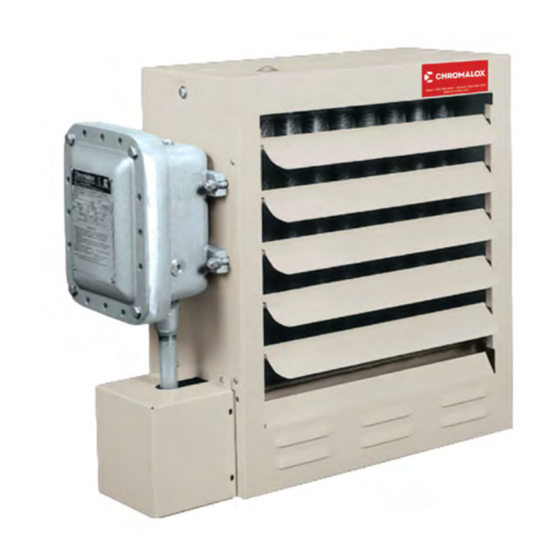
- Page 1 Installation, Operation and Maintenance Instructions CXH-A/B Hazardous Location Forced-Air Heater PF490CE-3 161-302421-007 August 2020 © 2020 Chromalox,...
-
Page 2: Table Of Contents
Table of Contents 1. Introduction 2. Safety 3. Specifications and Product Identification 4. Mechanical Installation 5. Electrical Installation 6. Operation 7. Preventative Maintenance and Repair 8. Troubleshooting 9. Warranty © 2020 Chromalox,... -
Page 3: Introduction
1. Introduction This document contains safety, installation, operation, maintenance, and troubleshooting information for model CXH-A/B unit heaters. Always check www.chromalox.com to ensure you have the latest revision of this document. Revision date is listed on the cover page. 2. Safety... -
Page 4: Specifications And Product Identification
3. Specifications and Product Identification Table A: Operating Performance Note: Performance data is based on results of controlled testing. Actual performance may vary depending on application. © 2020 Chromalox,... - Page 5 Model CXH-A/B heaters have an EC type examination as well as IECEx and EAC certificates issued by Intertek and have been approved to the following standards • EN 60079-0:2012+A11:2013 • EN 60079-1:2014 • IEC 60079-0:2011 (Ed. 6) • IEC 60079-1:2007-04 (Ed. 6) © 2020 Chromalox,...
- Page 6 3. Specifications and Product Identification Cont. © 2020 Chromalox,...
-
Page 7: Mechanical Installation
For best performance, locate heaters according to figure 1. was ordered. If listing does not meet hazardous location re- This will promote optimal air circulation and eliminate hot or quirements, contact Chromalox immediately. cold spots. Heaters should blow air parallel to exposed walls •... - Page 8 Figure 2: Maximum Out of Plane Dimensions Figure 3: Installation Clearances Figure 4: Mounting Holes Dimensions in. (mm) Heater Model 17-5/8 (447.7) CXH-A/B-03S to CXH-A/B-10S 21-5/8 (533.4) CXH-A/B-10M to CXH-A/B-20M 25-5/8 (635) CXH-A/B-25L to CXH-A/B-35L © 2020 Chromalox,...
-
Page 9: Electrical Installation
(18) x M12 cover bolts on the main enclosure. Once re- moved, the (3) mains wires should be connected directly to the heater contactor or circuit breaker (if equipped). See figures 5 and 6 for connection points. Figure 5: Mains Power Conduit/Cable Entries © 2020 Chromalox,... - Page 10 5. Electrical Installation Cont. Diagram 1 © 2020 Chromalox,...
- Page 11 15.5 CXH-A/B-15 18.5 23.2 CXH-A/B-20 24.5 30.7 CXH-A/B-25 30.9 38.7 CXH-A/B-30 36.9 46.2 CXH-A/B-35 42.9 53.7 CXH-A/B-03 CXH-A/B-05 CXH-A/B-07 CXH-A/B-10 10.4 13.0 CXH-A/B-15 15.2 19.0 CXH-A/B-20 20.0 25.0 CXH-A/B-25 24.7 30.9 CXH-A/B-30 29.6 37.0 CXH-A/B-35 34.4 43.0 © 2020 Chromalox,...
-
Page 12: Operation
• To gain access, remove the four sheet metal screws holding the sheet metal cover in place and unthread the cast aluminum enclosure lid. © 2020 Chromalox,... - Page 13 6. Operation Cont. Optional Integral Thermostat • Do not tamper with or remove thermostat terminal cover. Ther- mostat may only be serviced by Chromalox personnel. • Thermostats have a set range from 50-90°F (10-32°C). • To set the thermostat rotate dial to desired temperature...
- Page 14 Maintenance and repairs should be performed by quali- flame paths is located, do not repair. Take unit out of fied personnel only. service immediately and contact Chromalox to schedule service. • Improper maintenance or repair can result in injury and •...
- Page 15 8. Repair and Replacement © 2020 Chromalox,...
- Page 16 Motor Splice Box 14. Removal of fan blade does not require that the motor wiring be disturbed. To clean, service or change the fan blade proceed as follows: © 2020 Chromalox,...
- Page 17 E for proper torque spec. Table E - Flameproof Enclosure Bolt Torque Bolt Torque Bolt Torque Enclosure Bolt Size Bolt Grade (ft-lbs) (N-M) Control Enclosure 7/16-14 UNC-2A SAE 8 70.5 Thermostat Enclosure 5/16-18 UNC-2A SAE 7 24.4 Heating Element Terminal Housing © 2020 Chromalox,...
- Page 18 To remove pilot lights, unscrew them from the enclosure once wires are disconnected. Pilots lights are equipped with fusing. Fuses must be replaced with equivalent rated models. Only replace electrical components with those that are factory supplied and have an equivalent rating. © 2020 Chromalox,...
- Page 19 8. Repair and Replacement Cont. © 2020 Chromalox,...
-
Page 20: Troubleshooting
Check for burn marks on the contactor terminals Contactor is chattering (turning loose connections / short in and look for frayed or loose wires. Replace contac- on/off rapidly) wiring tor. Note: Chromalox document PF506 provides additional information regarding troubleshooting. © 2020 Chromalox,... - Page 21 Chromalox, Inc. 103 Gamma Drive Pittsburgh, PA 15215 .chromalox.com © 2020 Chromalox,...
Need help?
Do you have a question about the CXH-A/B Series and is the answer not in the manual?
Questions and answers