Table of Contents
Advertisement
Quick Links
Advertisement
Table of Contents

Related Manuals for Auto Crane HARD WIRED SERIES


Summary of Contents for Auto Crane HARD WIRED SERIES
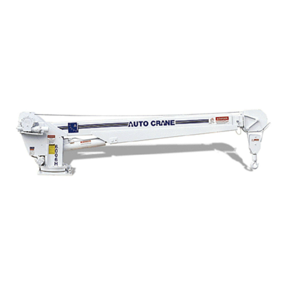
- Page 1 6006H-CA HARD WIRED SERIES OWNERS MANUAL Manual No. 366901000 Rev. 07/26/2004 Serial No. __________________ Mailing Address: P.O. Box 580697 Tulsa, OK 74158-0697 Physical Address: Phone (918) 836-0463 4707 N. Mingo Rd. Fax (918) 834-5979 Tulsa, OK 74117-5904 http://www.autocrane.com...
- Page 3 Serial No.: Date Product Delivered: Date Processed:* VIN # * For Auto Crane use only ONE REGISTRATION FORM PER UNIT (CRANE OR BODY) Registration form must be mailed or faxed within 15 days of customer installation. Mail to: Warranty Department Auto Crane Company P.O.
- Page 5 6006H HARD WIRED SERIES OWNER’S MANUAL – REVISION RECORD Section(s) Revision Description of Change Date Page(s) 09/02/03 Last page New 2-year warranty policy to replace 1-year warranty policy 07/26/04 Pages 3-2.0.0, 5- Added voltage drop relay circuit 1.0.0, 6-1.0.0, 6-...
- Page 7 ♦ Attempt to lift or drag a load from the side! The boom can fail far below its rated capacity. ♦ Weld, modify, or use unauthorized components on any Auto Crane unit! This will void any warranty or liability. Also failure of the crane may result.
-
Page 9: Table Of Contents
TABLE OF CONTENTS 6006H HARD WIRED SERIES INTRODUCTION 1-1.0.0 SAFETY TIPS AND PRECAUTIONS 2-1.0.0 OPERATING PRACTICES & WARNINGS 2-2.0.0 OPERATION OF UNIT / OUTRIGGERS 2-3.0.0 QUALIFCATIONS FOR OPERATORS 2-4.0.0 INSPECTION, TESTING, & MAINTENCE 2-7.0.0 DECAL SECTION 2-12.0.0 GENERAL DIMENSIONS 3-1.0.0 MOUNTING AND INSTALLATION 3-2.0.0... -
Page 11: Introduction
6006H crane are included on the General into the solution of an equipment problem. If, Dimension Drawing. Rotation and turning radius through no fault of Auto Crane Company, it is are also listed on that drawing. necessary to send an experienced factory... -
Page 12: Safety Tips And Precautions
WARNING! Auto Crane Company cranes are not designed or intended for use in lifting or moving persons. Any such use shall be considered to be improper and the seller shall not be responsible for any claims arising there from. - Page 13 --- IMPORTANT --- SAFETY TIPS AND PRECAUTIONS 31. Always store the crane in its stowed position for 41. Do not push down on anything with boom transportation. extensions, lift or outer boom function. 32. Remember the overall height of the entire unit for 42.
-
Page 14: Operating Practices & Warnings
Contact your local Distributor or the contacting electric lines. Do not use crane within 10 Auto Crane factory if any questions arise. feet (3.05m) of electric power lines carrying up to 50,000 volts. One foot additional clearance is required 3. -
Page 15: Operation Of Unit / Outriggers
Activate any area). crane power switches. For Auto Crane units 13. Return outriggers to stowed position. Make sure they requiring battery and hydraulic operation, engage are pinned in place or jacklegs are returned to emergency brake, place gear selector in neutral, compartment. -
Page 16: Qualifcations For Operators
QUALIFICATIONS FOR AND CONDUCT OF OPERATORS AND OPERATING PRACTICES OPERATORS tendencies to dizziness or similar undesirable characteristics. 1. Crane operation shall be limited to personnel with 8. In addition to the above listed requirements, the the following minimum qualifications: operator shall: A. - Page 17 QUALIFICATIONS FOR AND CONDUCT OF OPERATORS AND OPERATING PRACTICES The operator shall be familiar with the equipment 1. There is no sudden acceleration or deceleration of the moving load. and its proper care. If adjustments or repairs are necessary, the operator shall report the same 2.
- Page 18 QUALIFICATIONS FOR AND CONDUCT OF OPERATORS AND OPERATING PRACTICES MISCELLANEOUS 25. In transit with no load and boom lowered the clearance shall be specified in Table 1. OPERATING NEAR ELECTRICAL POWER LINES 26. A qualified signalperson shall be assigned to observe the clearance and give warning before approaching the above limits.
- Page 19 INSPECTION, TESTING AND MAINTENANCE GENERAL INSPECTION CLASSIFICATION G. electrical apparatus for malfunctioning, signs of excessive deterioration, dirt moisture accumulation 1. Initial inspection. Prior to initial use, all new, H. hydraulic system for proper oil level and leaks altered, modified or extensively repaired cranes daily shall be inspected by a designated person to insure compliance with provisions of this...
- Page 20 INSPECTION, TESTING AND MAINTENANCE GENERAL 13. Hydraulic and pneumatic pumps and motors 19. A crane which has been idle for a period of inspection. over six months shall be given a complete inspection conforming with the initial-regular- A. loose bolts or fasteners frequent inspection requirements.
- Page 21 INSPECTION, TESTING AND MAINTENANCE GENERAL 22. Test loads shall not exceed 110% of the 29. Repairs or replacements shall be provided as manufacturer's load ratings. needed for operation. 23. Written reports shall be maintained showing The following are examples: test procedures and confirming the adequacy A.
- Page 22 INSPECTION, TESTING AND MAINTENANCE GENERAL B. Care shall be taken when inspecting sections ROPE REPLACEMENT of rapid deterioration such as flange points, crossover points, and repetitive pickup points 33. No precise rules can be given for determination on drums. of the exact time for replacement of rope, since 32.
- Page 23 INSPECTION, TESTING AND MAINTENANCE GENERAL H. Replacement rope shall have a strength rating be cut to prevent unlaying of the strands. On at least as great as the original rope furnished pre-formed rope, one seizing on each side of or recommended by the crane manufacturer. the cut is required.
-
Page 24: Decal Section
SAFETY DECAL SECTION 6006H HARD WIRED SERIES PART NO.: 40579000 DECAL: OPERATING INSTRUCTIONS FUNCTION: To inform the operator of the proper procedure to follow for safe operation of the crane. USED ON: All Cranes QUANTITY: PLACEMENT: Right side plate PART NO.:... - Page 25 SAFETY DECAL SECTION 6006H HARD WIRED SERIES PART NO.: 040529000 DECAL: ELECTROCUTION HAZARD FUNCTION: To inform the operator of the hazard involved with contacting electrical power lines with crane boom. USED ON: Articulated & Stiff Boom Cranes QUANTITY: PLACEMENT: Both sides of end of lower boom PART NO.:...
- Page 26 SAFETY DECAL SECTION 6006H HARD WIRED SERIES PART NO.: 040587000 USED ON: All cranes equipped with a load sensor. DECAL: LOAD SENSOR, DON'T TAMPER QUANTITY: FUNCTION: To inform the operator that the load PLACEMENT: On the lift cylinder near the load...
- Page 27 DECAL LAYOUT 6006H HARD WIRED SERIES ITEM NO. QTY. PART NO. DESCRIPTION 320318001 DECAL ANGLE IND RIGHT 040579 DECAL OPERATION INSTRUCTIONS 040632 DECAL WARNING - OVERLOAD 040580 DECAL TRAINED OPERATOR 040529 DECAL POWER LINE HAZARD 040517 DECAL STAY CLEAR OF BOOM...
-
Page 29: General Dimensions
GENERAL DIMINEIONS 6006H HARD WIRED SERIES 23 1/16" 10 1/16" R23 1/8" 22 7/16" 8 1/16" 37 1/16" 33 3/16" 26 9/16" 13 1/8" (4 PLCS) #10 SAE RETURN FITTING TOWARD CAB >>> 16 3/4" 14 3/4" #8 SAE PRESSURE FITTING 14 3/4"... -
Page 30: Mounting And Installation
MOUNTING AND INSTALLATION 6006H HARD WIRED SERIES 1. Check to make sure the following items are with your crane. ITEM PART NO. DESCRIPTION 366063000 TRAVELING BLOCK, 6006H 366901000 OWNERS MANUAL 015104000 BOLT 7/8 NF x 5" GRADE 8 (4 REQ'D) - Page 31 13. Load test the crane to ensure proper functioning and truck stability 14. Make certain the owner’s manual is delivered to the customer. 15. For additional help: call the service department at the Auto Crane Company. (918) 836-0463 (Tulsa, Oklahoma)
- Page 32 13. Load test the crane to ensure proper functioning and truck stability 14. Make certain the owner’s manual is delivered to the customer. 15. For additional help: call the service department at the Auto Crane Company. (918) 836-0463 (Tulsa, Oklahoma)
- Page 33 LUBRICATION & MAINTENANCE SCHEDULE 6006H HARD WIRED SERIES SERVICE WEEKLY 3 MOS 6 MOS YEAR NOTES PERFORMED INSPECT HOOK & LATCH FOR LOAD HOOK DEFORMATION, CRACKS, & CORROSION MAKE SHURE CABLE IS WOUND CABLE DRUM EVENLY ON DRUM CHECK FOR FLATTENING, KINKS, HOIST / BOOM &...
- Page 34 2. Once a bolt has been torqued to its rated capacity and then removed; the bolt should be replaced with a new one. 3. Auto Crane Company recommends that this crane be serviced per “Crane Inspection Log” P/N 999978. These logs should be filled in at the intervals noted and kept as a permanent record.
-
Page 35: Pedestal Assembly
PEDESTAL ASSEMBLY 6006H HARD WIRED SERIES 68 69 36 37 38 54 56 55 18 17 HYDRAULIC VALVE KEY 32 31 PORT #1: HOIST DOWN PORT #2: HOIST UP PORT #3: ROTATION CCW PORT #4: ROTATION CW PORT #5: LIFT CYL EXTEND... - Page 36 PEDESTAL ASSEMBLY 6006H HARD WIRED SERIES ITEM NO. QTY. PART NO. DESCRIPTION 480847000 PEDESTAL WELD 160407 GEAR BOX, ROTATION 366492 PIN 1.25<MOD-DIAM> X 3.00 LG 366342 CYL, LIFT 366365000 VALVE CONTROL ASSY 366333 BEARING, SPHERICAL 1.25 ID 480023002 BEARING, ROTATION...
- Page 37 PEDESTAL ASSEMBLY 6006H HARD WIRED SERIES ITEM NO. QTY. PART NO. DESCRIPTION 642908 CORD CONNECTOR 020000 10 SAE FLAT WASHER 019800 10 SPLIT LOCK 330679 SCW BT HD SOCKET 10-32 X 1/2 011202 SCW HX HD 1/2-20 X 2 3/4...
- Page 39 PEDESTAL ASSEMBLY 6006H HARD WIRED SERIES ITEM NO. QTY. PART NO. DESCRIPTION 10 SAE FLAT WASHER 20000 19800 10 SPLIT LOCK 330679 SCW BT HD SOCKET 10-32 X 1/2 11202 SCW HX HD 1/2-20 X 2 3/4 NUT HX HVY 1/2 NF...
-
Page 40: Boom Assembly
BOOM ASSEMBLY 6006H HARD WIRED SERIES Cylinder Seal Kit - # 366331001 Counterbalance Cartridge - # 480188000 5-4.0.0 5/28/2003... - Page 41 BOOM ASSEMBLY 6006H HARD WIRED SERIES ITEM NO. QTY. PART NO. DESCRIPTION 480831000 BOOM WELDMENT, LOWER 366385 PLATE, LOWER BOOM PAD COVER 366201 WEAR PAD 3 .75 X 2.00 X .313 480871000 BOOM WELDMENT, UPPER 366331 CYLINDER EXTENSION 480876000 BOOM WELDMENT MID...
-
Page 42: Rotation Gear Box
ROTATION GEAR BOX P/N: 160407 5-6.0.0 5/28/03... - Page 43 ROTATION GEAR BOX P/N: 160407 ITEM PART NO. DESCRIPTION 480240000 ADAPTER 480241000 BUSHING 480242000 CAP BEARING 480243000 COVER 480244000 GEAR R.H. 480237000 HOUSING GEAR 480246000 480247000 SHAFT OUTPUT 480248000 WASHER THRUST 480249000 WORM R.H. 480251000 BEARING BALL 480252000 BEARING NEEDLE 480253000 BEARING NEEDLE 480254000...
-
Page 44: Hoist Assembly
HOIST ASSEMBLY 6006H HARD WIRED SERIES 5-8.0.0 5/28/2003... - Page 45 HOIST ASSEMBLY 6006H HARD WIRED SERIES ITEM PART NO. DESCRIPTION 234189 DRUM ASSEMBLY 306042 PISTON BRAKE 338300 END BEARING MOTOR 338301 END BEARING GEAR HOUSING 338302 HOUSING BRAKE 346045 PIN BRAKE 357513 INPUT SHAFT SUN GEAR 474065 PLATE TIE 402120...
- Page 47 HOIST ASSEMBLY 6006H HARD WIRED SERIES ITEM PART NO. DESCRIPTION 474111 PLATE SEPERATOR 486080 SEAL GEAR HOUSING 490037 SNAP RING 494110 SPRING BRAKE 494112 SPEING 509019 TUBE ASSEMBLY 516028 VALVE MOTOR CONTROL 518037 THRUST WASHER 518047 THRUST WASHER 518052 THRUST WASHER...
-
Page 49: General Assembly
GENERAL ASSEMBLY 6006H HARD WIRED SERIES RETRACT PORT #8 EXTEND PORT #7 3 6 5 ITEM NO. QTY. PART NO. DESCRIPTION 366302000 PEDESTAL ASSY, 6006H HARD WIRED 366491 PIN 2 DIA X 10.5 LG 366492 PIN 1.25 DIA X 3.00 LG... -
Page 50: Electrical Schematic
ELECTRICAL SCHEMATIC HARD WIRED CRANE JUNCTION BOX 12 PIN CONNECTOR GREEN GREEN HOIST UP RED/BLACK RED/BLACK RED/WHITE BLACK WHITE/BLACK ORANGE ORANGE ROT SW CW HOIST DOWN WHITE ROT SW CCW BLUE BLUE BLACK GREEN/BLACK GREEN/BLACK ROTATE CCW ORANGE/BLACK ORANGE/BLACK WHT/RED BLACK ROTATE CW GREEN... - Page 51 MAIN WIRING HARNESS 10.0" WHT/RED 10.0" 5.0" PRESS SWITCH -1 RED/WHT WHT/RED 4.0" 10.0" 10.0" A2B SWITCH RED/WHT 9.0" SOLDER TIPS ROTATE SWITCH BOOM LIMIT RED WIRE WHT/RED NOT USED 3.5" 5.0" WHT/RED 4.5" RED/WHT RED/WHT 5.0" 2.5" FUNCTION WIRE COLOR NOTES ITEM NO.
-
Page 52: Pendant Assembly
PENDANT ASSEMBLY, 8 FUNCTION 6006H HARD WIRED SERIES 6-3.0.0 5/28/2003... - Page 53 PENDANT ASSEMBLY, 8 FUNCTION 6006H HARD WIRED SERIES ITEM PART NO. DESCRIPTION 480501 HOUSING, PROP. PENDANT MACHINED 480518 DECAL/COVER PLATE NUT (INCLUDED WITH SWITCH) 640300 BOOT, TOGGLE 480567 CORD GRIP, HUBBELL CONNECTOR 002607 SCREW, HX HD #10-24 NC X 3/4 LG...
- Page 55 PENDANT CABLE ASSEMBLY 6006H HARD WIRED SERIES ITEM PART NO. DESCRIPTION 366098 PLUG, CONNECTOR 480515 CLAMP, CABLE 480594 CABLE, CONDUCTOR (19 COND) 000101 TERMINAL RING #6 / 14-16 GA 480510 CONNECTOR, BULLET, FEMALE 002012 TERMINAL RING #6 / 18-22 GA 6"...
-
Page 56: Junction Box Assembly
JUNCTION BOX ASSEMBLY 6006H HARD WIRED SERIES FUNCTION 19 PIN 8 PIN 12 PIN WIRE COLOR BOOM UP HOIST UP GREEN ROTATE CW ORANGE ENGINE FAST RED/WHITE ROTATE CCW BLACK HOIST DN RED/BLACK BOOM DN BLUE RETRACT ORANGE/BLACK EXTEND GREEN/BLACK... - Page 57 JUNCTION BOX ASSEMBLY 6006H HARD WIRED SERIES ITEM NO. QTY. PART NO. DESCRIPTION 366470000 JUNCTION BOX 366095 RECEPTACLE, 19 PIN 366523001 HOUSING, DEUTSCH 8-PIN RECEPTACLE 480594001 CABLE, PENDANT, 16/10 SO BLACK 366471000 COVER, JUNCTION BOX 366524001 HOUSING, DEUTSCH 12-PIN RECEPTACLE...
- Page 58 HYDRAULIC SCHEMATIC Secondary Extension Hoist Rotation Lift Primary Extension 4 GPM .015 Proportional 7-1.0.0 528//2003...
- Page 59 HYDRAULIC SCHEMATIC Notice: Counterbalance Valve Adjustment ♦ With PTO disengaged and boom properly ♦ In an EMERGENCY situation when it supported, remove the plug on the becomes necessary to lower the boom counterbalance valve. Install a pressure without flow present, the CB valve gauge (0-3000 PSI) into the port.
- Page 60 HYDRAUIC CONTROL VALVE 6006H HARD WIRED SERIES 7-3.0.0 528//2003...
- Page 61 HYDRAUIC CONTROL VALVE 6006H HARD WIRED SERIES ITEM A/C P/N DESCRIPTION 366365001 COIL 366365002 PROP VALVE 320725005 COIL 366365003 FLOW CONTROL 366365004 RELIEF VALVE SV1,SV2 366365005 CART VALVE SV3,SV4,SV5 320725001 CART VALVE ORF1 ORIFICE PLUG PLG4 PORT PLUG NOT SHOWN...
- Page 62 PROPORTIONAL VALVE CONTROLLER/AMP 6006H HARD WIRED SERIES RISING RAMP FALLING RAMP DITHER AMPLITUDE DITHER FREQ OUTPUT: 2000mA MAX MINIMUM CURRENT I-MIN SETTING: 0 TO 500mA I-MAX SETTING: 600 TO 2000mA CABLE LENGTH: 6 FEET MAXIMUM CURRENT Minimum current adjustment: Current is factory set at 150 mA, no adjustment required at installation. If adjustment is required, set the minimum current before setting the maximum current.
- Page 63 NOTES...
-
Page 65: Load Chart
LOAD CHART 6006H SERIES 8-1.0.0 5/28/2003... -
Page 67: Warranty
2 YEAR PARTS AND LABOR Auto Crane will warranty to the consumer for a period of (2) years parts and labor from the date of purchase. Each new Auto Crane unit they sell will be free under normal use and service from defects in material and workmanship.
Need help?
Do you have a question about the HARD WIRED SERIES and is the answer not in the manual?
Questions and answers