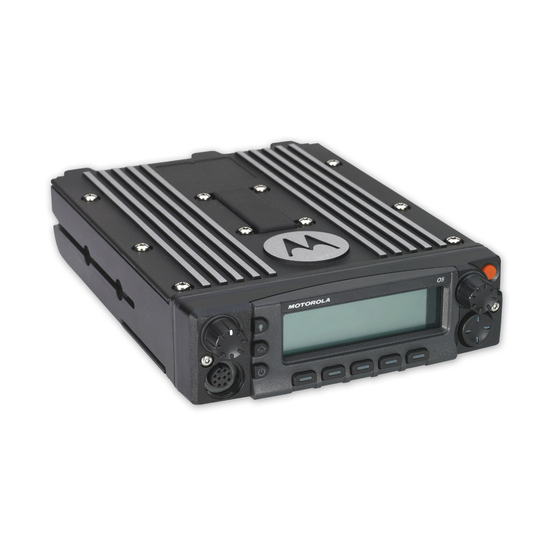
Motorola ASTRO APX O5 User Manual
Two-way radios, mobile radio control head
Hide thumbs
Also See for ASTRO APX O5:
- User manual (152 pages) ,
- Installation manual (95 pages) ,
- User manual (138 pages)
Table of Contents
Advertisement
Quick Links
Advertisement
Table of Contents

Related Manuals for Motorola ASTRO APX O5


Summary of Contents for Motorola ASTRO APX O5
- Page 3 Emergency button. *PMLN5592G* MOTOROLA, MOTO, MOTOROLA SOLUTIONS and the Stylized M logo are trademarks or registered trademarks of Motorola Trademark Holdings, LLC and are used under license. All other trademarks are the property of their respective owners. © 2009–2011, 2013, 2015 by Motorola Solutions, Inc.
- Page 4 Direct radio-to-radio communication or On = Secure operation. Sending an Emergency Call (Trunking Only) communication through a repeater. Off = Clear operation. On = Direct Blinking = Receiving an encrypted voice Press Emergency button. Off = Repeater call. A tone sounds and the display alternates On = AES Secure operation.
-
Page 5: Table Of Contents
Contents Documentation Copyrights...15 Disclaimer........16 Declaration of Conformity......8 Important Safety Information..10 Getting Started....... 17 How to Use This Guide........17 Notations Used in This Manual......17 Software Version......11 Additional Performance Enhancement..18 Notice to Users (FCC and Industry ASTRO 25 Enhanced Data....18 Canada)............11 Dynamic System Resilience (DSR).. - Page 6 Turning On the Radio........20 Keypad Characters – Numeric Adjusting the Volume........21 Mode..........32 Validating Compatibility During Power Up..21 Keypad Characters – Hexadecimal Mode..........33 Push-To-Talk (PTT) Button......35 Identifying Radio Controls.... 22 Radio Parts and Controls.......22 Identifying Status Indicators..36 Control Head and Microphone.... 22 Programmable Features........
- Page 7 Saving a Zone and a Channel to a Selective Call (ASTRO Button..........49 Conventional Only)......57 Receiving and Responding to a Radio Call... 50 Talkgroup Call Feature Receiving and Responding to a (Conventional Operation Only)..58 Talkgroup Call........50 Sending a Status Call......59 Receiving and Responding to a Responding to the Dynamic Private Call (Trunking Only)...51...
- Page 8 Viewing and Changing the Priority Sending an Emergency Alarm with Status..........73 Emergency Call......81 Scan...............73 Sending a Silent Emergency Alarm..81 Turning Scan On or Off.......73 Special Considerations for Turning Scan On While Emergencies........82 Disregarding the Squelch Code Automatic Registration Service (ARS)...82 (Conventional Channels Only)..
- Page 9 Accessing the Outdoor Location Blank..........117 Feature........104 Tx Inhibit........... 117 Turning Off GPS....... 105 PTT Tx Inhibit........117 Saving a Waypoint......105 Required........... 117 Viewing a Saved Waypoint....106 Soft Power Off........117 Editing the Alias of a Waypoint..106 Ignition Only Power Up..... 117 Editing the Coordinates of a Using Emergency Power Up.....118 Waypoint........
- Page 10 Channel Change on Off Hook on All Cleaning the External Surface of Channels..........125 the Radio........141 Low Voltage Threshold Warning....127 Cleaning the External Plastic Utilities............127 Surface........141 Viewing Recent Calls......127 Selecting the Power Level....128 Accessories........143 Selecting a Radio Profile....129 Controlling the Display Backlight..
- Page 11 MOTOROLA COMMUNICATION PRODUCTS........... 154 I. WHAT THIS WARRANTY COVERS AND FOR HOW LONG:......154 II. GENERAL PROVISIONS:....... 155 III. STATE LAW RIGHTS:......156 IV. HOW TO GET WARRANTY SERVICE:.156 V. WHAT THIS WARRANTY DOES NOT COVER:..........156 VI. PATENT AND SOFTWARE PROVISIONS:........157 VII.
-
Page 12: Declaration Of Conformity
This declaration is applicable to your radio only if your radio is labeled with the FCC logo shown below. Declaration of Conformity Per FCC CFR 47 Part 2 Section 2.1077(a) Responsible Party Name: Motorola Solutions, Inc. Address: 1303 East Algonquin Road, Schaumburg, IL 60196-1078, U.S.A. Phone Number: 1-800-927-2744 Hereby declares that the product:... - Page 13 Class B Digital Device As a personal computer peripheral, this device complies with Part 15 of the FCC Rules. Operation is subject to the following two conditions: 1 This device may not cause harmful interference, and 2 This device must accept any interference received, including interference that may cause undesired operation. Note: This equipment has been tested and found to comply with the limits for a Class B digital device, pursuant to part 15 of the FCC Rules.
-
Page 14: Important Safety Information
Regulations. complete control of the radio. In this mode, the radio no longer responds to button and PTT For a list of Motorola-approved antennas and other presses nor will it unmute to voice activity. accessories, visit the following website: This mode is designed to receive and pass http://www.motorolasolutions.com/APX... -
Page 15: Software Version
• This device must accept any interference received, including interference that may cause undesired operation. • Changes or modifications made to this device, not expressly approved by Motorola, could void the authority of the user to operate this equipment. English... -
Page 16: Consignes De Sécurité Importantes
Cet émetteur radio a été approuvé par Industrie Canada pour utilisation avec une antenne approuvée Cette radio ne doit être utilisée qu'à des fins par Motorola offrant le gain maximal autorisé et professionnelles. Avant d'utiliser la radio, lisez le l'impédance requise pour le type d'antenne indiqué. Il... -
Page 17: Version Logicielle
Motorola, peuvent annuler le droit de l'utilisateur à Version logicielle utiliser cet équipement. Toutes les fonctions décrites dans les sections suivantes sont prises en charge par la version R14.00.00 ou les versions ultérieures du logiciel de la radio. Pour obtenir davantage de renseignements à propos des fonctions prises en charge, adressez-vous à... -
Page 18: Computer Software Copyrights
Motorola. Furthermore, the purchase of Motorola products shall not be deemed to grant either directly or by implication, estoppel, or otherwise, any license under the copyrights, patents or patent... -
Page 19: Documentation Copyrights
No duplication or distribution of this document or any portion thereof shall take place without the express written permission of Motorola. No part of this manual may be reproduced, distributed, or transmitted in any form or by any means, electronic or mechanical, for any purpose without the express written permission of Motorola. -
Page 20: Disclaimer
However, no responsibility is assumed for inaccuracies. Furthermore, Motorola reserves the right to make changes to any products herein to improve readability, function, or design. Motorola does not assume any liability arising out of the applications or use of any product or circuit described herein;... -
Page 21: Getting Started
damage to the equipment if not carefully Getting Started observed. Note: How to Use This Guide An operational procedure, practice, or condition and so on, which is essential to This User Guide covers the basic operation of the emphasize. APX Mobiles. The following special notations identify certain items. -
Page 22: Additional Performance Enhancement
Dynamic System Resilience (DSR) SecureNet allows user to perform secured DSR ensures the radio system is seamlessly communications on an Analog or Motorola Data switched to a backup master site dynamically in case Communication (MDC) channel. The MDC Over-the- of system failure. DSR also provides additional Air Rekeying (OTAR) feature will allow users to indication e.g. -
Page 23: Conventional Talkgroup And Radio Scan Enhancements
is available and portable radio coverage is either Note: intermittent or non-existent. User Selectable Talkgroups are not compatible with this Conventional Talkgroup Conventional Talkgroup and Radio Scan Enhancement. Enhancements What Your Dealer/System Administrator Can A few enhancements have been made to the Conventional Talkgroup at the system. -
Page 24: Preparing Your Radio For Use
Note: Preparing Your Radio for Use Pressing the Power On/Off Button before the LED lights up will be ignored. This section provides simple instructions to prepare If FAIL ##/## appears in the display, the your radio for use. radio will not function until the condition Turning On the Radio has been corrected. -
Page 25: Adjusting The Volume
radio is programmable by a qualified radio Press the Power On/Off Button to reset when the technician. display shows UPDATE DONE PLEASE RESET upon completion, or when the display shows UPDATE Adjusting the Volume FAILED PLEASE RESET when it fails to update. If the software updates are complete, the radio runs 1 To increase the volume, rotate the Volume Knob the usual power up operation. -
Page 26: Identifying Radio Controls
Identifying Radio Controls Radio Parts and Controls Control Head and Microphone Note: The microphone is not part of a radio. It is an optional accessory. Accessory Port (Microphone) Menu Select Button Menu Entries LED Indicators Navigation Button Accy 2-Dot Button Accy 1-Dot Button English... -
Page 27: Programmable Features
Accy No-Dot Button (Purple) Push-to-Talk (PTT) Button Programmable Features Orange Button Any reference in this manual to controls that are preprogrammed means that a qualified radio Mode Knob technician must use the radio programming software Indicators to assign a feature to a control. Power On/Off Button Your dealer can program the programmable buttons as shortcuts to radio functions or preset channels/... - Page 28 Call Response Allows you to answer a private Internet Protocol Display the Internet Protocol call or phone call. Address (IP) address, device name and status of the radio. Channel Selects a channel. Location Determines the current location Contacts Selects the Contacts menu. (latitude, longitude, time and Dynamic ID Allows you to edit the ASTRO...
- Page 29 Launches a specific feature Reprogram Notifies the dispatcher you with one single button-press. Request want a new dynamic You can setup as many as four (Trunking Only) regrouping assignment. separately programmed Request-To-Talk Notifies the dispatcher you buttons for four different (Conventional want to send a voice call.
-
Page 30: Assignable Settings Or Utility Functions
Assignable Settings or Utility Functions Site Lock/Unlock Locks onto a specific site. (Trunking Only) Changes the display brightness. Status (Astro 25 Sends data calls to the Trunking Only) dispatcher about a predefined Front/Rear Switches one of two control status. heads to be active at one time. -
Page 31: Menu Select Buttons
Advance Programmable Buttons • A short or long press of the relevant programmable buttons. This feature is to help you to shorten the process of applying certain common features. • Use the Menu Select Button ( Menu Select Buttons Note: Check with your dealer or system administrator for the list of features activated in your radio. -
Page 32: Home Button
individual feature sections in this manual for Accy No-Dot Button (Purple) further details on saving user-edited radio Accy 1-Dot Button settings or information. Accy 2-Dot Button button also can revert to home channel from any other zone and mode in the radio. Check with your dealer or system administrator for more information. -
Page 33: Volume Knob
Volume Knob The keypad functions in a manner similar to a standard telephone keypad when entering numeric Use this Volume Knob to adjust the volume of the digits. When the keypad is used to edit a list, each speakers by turning it clockwise or counterclockwise. key can generate different characters of the alphabet. -
Page 34: Keypad Characters - Lowercase Mode
Number of Times Key is Pressed Toggle between mixed case mode, uppercase mode and lowercase mode. Space Toggle between numeric and letter mode. Keypad Characters – Lowercase Mode Number of Times Key is Pressed & “ ‘ English... - Page 35 Number of Times Key is Pressed Toggle between mixed case mode, uppercase mode and lowercase mode. Space Toggle between numeric and letter mode. English...
-
Page 36: Keypad Characters - Numeric Mode
Keypad Characters – Numeric Mode Number of Times Key is Pressed & “ ‘ Space English... -
Page 37: Keypad Characters - Hexadecimal Mode
Number of Times Key is Pressed Toggle between numeric and letter mode. Keypad Characters – Hexadecimal Mode Number of Times Key is Pressed English... - Page 38 Number of Times Key is Pressed Not applicable Not applicable English...
-
Page 39: Push-To-Talk (Ptt) Button
• While a call is not in progress, the PTT button is Push-To-Talk (PTT) Button used to make a new call. See Methods to Make a Radio Call on page 52 for more information. The PTT button on the side of the microphone serves two basic purposes: •... -
Page 40: Identifying Status Indicators
On – Radio is currently configured for di- Identifying Status Indicators rect radio-to-radio communication (dur- ing conventional operation only). Status Icons Off – Radio is connected with other ra- The liquid crystal display (LCD) of your radio shows dios through a repeater. the radio status, text entries, and menu entries. - Page 41 H – Radio is set at High power. Off – Clear operation. Blinking – Receiving an encrypted Scan voice call. Radio is scanning a scan list. GPS Signal Priority Channel Scan On – Feature is enabled and signal is available. Blinking dot –...
-
Page 42: Text Messaging Service (Tms) Indicators
Data Activity Lowercase Data activity is present. Indicates that the text entry is currently in lowercase mode. Hexadecimal Lowercase Predictive Indicates that the text entry is currently in hexadecimal mode. Indicates that the text entry is currently in lowercase and with predicted words Numeric shown at the bottom of the screen. -
Page 43: Tms Status Icons
here help you to work more efficiently with TMS The selected text message in the Inbox feature. See Text Messaging Service (TMS) on page has been read. 86 for more information. TMS Status Icons Normal Message The following icons appear on the radio’s display User is composing a message with normal when you send and receive text messages. -
Page 44: Tms Menu Options
Menu Description/Function • The “Request Reply” feature is toggled Option on before the message is sent. • Messages in the Inbox folder are flag- Saves the messages you have edited to SAVE ged with “Request Reply”. the Draft folder. Brings you to the sent messages screen. SENT Priority Status and Request Reply Creates a new message. -
Page 45: Led Indicator
Menu Description/Function Red LED Option Yellow LED Cancel the delete all messages options. Green LED Brings you to the Options main screen. OPTN Replies to a message. RPLY Solid red Radio is transmitting. Selects a predefined message or ad- Rapidly blinking Radio has failed the self test dress. -
Page 46: Intelligent Lighting Indicators
Rapidly blinking Radio is on a Priority-One green channel while in the Scan List Programming mode. Intelligent Lighting Indicators This feature temporarily changes the display backlight color and the alert text background color of the radio to help signal that a radio event has occurred. Note: This feature must be preprogrammed by a qualified radio technician. -
Page 47: Alert Tones
Backlight and Bar Notification When Color Green Call Alerts The radio receives a private call. The radio receives a phone call. The radio receives a call alert. The radio receives a selective call. The radio enters Geofence. Alert Tones Your radio uses alert tones to inform you of the condition of your radio. The following table lists these tones and when they occur. - Page 48 You Hear Tone Name Heard Long, Low- Time-Out Timer Timed Out After time out. Pitched Tone Talk Prohibit/PTT Inhibit (When PTT button is pressed) transmissions are not allowed. Lack of Voice PTT Time out When the radio ends your call after it detected there are lack of voice for 5 seconds after the PTT is pressed and hold.
- Page 49 You Hear Tone Name Heard Central Echo When central controller has received a request from a radio. Long, Medium- Volume Set When volume is changed on a quiet channel. Pitched Tone Emergency Exit When exiting the emergency state. A Group of Me- Failsoft When the trunking system fails.
- Page 50 You Hear Tone Name Heard Enhanced Call Sent When waiting for target of Private Call to answer the call. Phone Call Received When a land-to-mobile phone call is received. Gurgle Dynamic Regrouping (When PTT button is pressed) a dynamic ID has been received. Talk Permit (When PTT button is pressed) is verifying with the system for ac- cepting its transmissions.
-
Page 51: General Radio Operation
d) Press the PTT button to transmit on the General Radio Operation displayed zone channel. Selecting a Zone Selecting a Radio Channel Your radio must be preprogrammed to allow you to A channel is a group of radio characteristics, such as use this feature. -
Page 52: Selecting A Channel Via Channel Search Button
e) Press the PTT button to transmit on the To exit this procedure, press the Menu Select displayed zone channel. button directly below CNCL. The display shows SEARCHING. Once found, the Selecting a Channel via Channel Search display shows the matched channel name and the Button radio changed its transmission to the selected channel. -
Page 53: Saving A Zone And A Channel To A Softkey
• Softkeys Short press of the programmed softkey changes your current transmission to the zone • Programmable buttons and keypad buttons (digit 0 and channel programmed in this softkey. to 9) Saving a Zone and a Channel to a Button Note: Your radio must be preprogrammed to allow You can save the frequent used zone and channel to... -
Page 54: Receiving And Responding To A Radio Call
Receiving and Responding to a Talkgroup Call Receiving and Responding to a Radio Call To receive a call from a group of users, your radio Once you have selected the required channel and/or must be configured as part of that talkgroup. zone, you can proceed to receive and respond to When you receive a talkgroup call (while on the calls. -
Page 55: Receiving And Responding To A Private Call (Trunking Only)
Receiving and Responding to a Private Call (Trunking 2 Press and hold the PTT button to talk. Release the Only) PTT button to listen. A Private Call is a call from an individual radio to 3 Press to hang up and return to the Home another individual radio. -
Page 56: Methods To Make A Radio Call
expires, your radio exits the call with Menu • The Contacts list (see Contacts on page 66). Inactive Exit tone. Note: When you receive a Telephone Call, you hear a The radio automatically exits the feature, if the telephone-type ringing and the LED blinks green. The feature inactivity timer is enabled, when the backlight of the screen turns green.The display shows radio is left idle and the timer expires. -
Page 57: Making A Private Call (Trunking Only)
• For ASTRO Conventional system, the LED • To access this feature via the menu, proceed lights up solid red. The display shows the to the next step. talkgroup alias or ID. • For Trunking system, the LED lights up solid or to CALL, and press the Menu Select button red. -
Page 58: Making A Telephone Call (Trunking Only)
When you are connected, the display shows the or to PHON, and press the Menu Select button ID of the target radio. directly below PHON. If no acknowledgment is received, the display The display shows the last transmitted or received shows NO ACKNOWLEDGE. -
Page 59: Switching Between Repeater Or Direct Operation Button
The display shows REPEATER MODE if the radio is 7 Press to return to the Home screen. currently in Repeater mode. Alert Tones on page 43 for more information if The display shows DIRECT MODE and the Talkaround your call is NOT answered. icon if the radio is currently in Direct mode (during conventional operation only). -
Page 60: Monitoring Conventional Mode
d) If you hear no activity, press and hold the PTT 1 To activate monitoring, perform one of the button to start your conversation. following actions: • At Home mode where the default zone and • Monitoring a Channel in Trunked Modes: channel are being displayed, or to MON and a) Lift the microphone off hook. -
Page 61: Advanced Features
and to eliminate the annoyance of having to listen to Advanced Features conversations that are of no interest to you. Receiving a Selective Call Advanced Call Features When you receive a Selective Call, you hear two alert Calling a Phone Not in the List tones and the LED lights up solid yellow. -
Page 62: Talkgroup Call Feature (Conventional Operation Only)
Selective Call. See Making a Selective Call • or to the required ID. on page 58. • Use the keypad to enter the required ID. Making a Selective Call 4 Hold the microphone vertically 1 to 2 inches (2.5 to 5.0 cm) from your mouth. -
Page 63: Sending A Status Call
Note: If the encryption key that is associated to the new Encryption keys are associated to talkgroups. Talkgroup is not allowed, you hear a momentary When talkgroups are associated, encryption key fail tone and the display shows ILLEGAL KEY. keys are changed by changing the active 4 Press talkgroup. -
Page 64: Responding To The Dynamic Regrouping Feature (Trunking Only)
feature is typically used during special operations and 2 Perform one of the following actions: is enabled by a qualified radio technician. • or to the required status. You will not notice whether your radio has this feature • Use the keypad to enter a number enabled until a dynamic regrouping command is sent corresponding to the location in the status list. -
Page 65: Dynamic Zone Programming (Dzp)
Perform one of the following actions: Select Select-enabled radios are free to Enabled change to any available channel, • Press the preprogrammed Reprogram including the dynamic-regrouping Request button to send reprogram request to channel, once the user has selected the dispatcher. the dynamic-regrouping position. - Page 66 around the working zones and channels. User can If you have selected Exit without selecting any also delete or update the list in the Dynamic Zone. Dynamic Zone Channels list, the display returns to Home screen without any changes. Entering the Dynamic Zone to Select a Dynamic Channel Saving a Channel in the Dynamic Zone from List or to Zone then press the Menu Select button...
-
Page 67: Multiple Control Head Features
The display shows Select Chan screen. If the channel deleted is the Home channel, the Home screen shows <Zone Name>+”Blank”. to the required channel. Press the Menu Select button directly below SEL. Multiple Control Head Features The display shows Channel updated. This feature allows your transceiver to control a 6 Press the Menu Select button directly below Exit combination of up to four O2 and O7 control heads on... -
Page 68: Setting The Id Of The Initial Control Head
Setting the ID of the Initial Control Head All Active Mode This feature allows you to setup the control head in The All Active mode enables all connected control the Front Panel Programming (FPP) mode. During heads attached to the radio to operate concurrently the setup, the control heads are defined as Control with each other. -
Page 69: One Active Mode
control head releases PTT button. This can be made Note: on any attached control head. In the One Active mode, if more than 2 control heads are present upon power up, the radio 1 Press the Menu Select button directly below INTC shows a FATAL error EXTRA CH on the display to activate the intercom feature of any of the of all attached control heads. -
Page 70: Contacts
Contacts This feature provides “address-book” capabilities on your radio. Each entry corresponds to an alias (name) or ID (number) that you use to initiate a call. Contact entries are alphabetically sorted according to ZONE CHAN entry alias. Each alias can have up to five IDs of different call types associated with it. -
Page 71: Making A Private Call From Contacts
Your radio also supports a maximum of 50 call lists. • Press the Menu Select button directly below Each list can store up to 100 IDs (numbers). CNTS and proceed to step 6. Note: or to CALL and press the Menu Select button Your radio is preprogrammed with a number of directly below SEL. -
Page 72: Adding A New Contact Entry
Adding a New Contact Entry or to the required channel and press the Menu Select button directly below OK. or to CNTS and press the Menu Select button directly below CNTS. or to NUMBER 1 and press the Menu Select The entries are alphabetically sorted. -
Page 73: Adding A Contact To A Call List
The entries are alphabetically sorted. or to ADD TO CALLLST or ADD TO PHONLST and press the Menu Select button directly below or to the entry you want to delete and press the SEL. Menu Select button directly below OPTN. 4 Perform one of the following actions: or to DEL and press the Menu Select button •... - Page 74 or to the entry you want to edit and press the or to the entry you want to edit and press the Menu Select button directly below OPTN. Menu Select button directly below OPTN. or to EDIT and press the Menu Select button or to EDIT and press the Menu Select button directly below SEL.
-
Page 75: Scan Lists
• Trunking Priority Monitor Scan List or to the entry you want to edit and press the • Conventional Scan List Menu Select button directly below OPTN. • Talkgroup Scan List or to EDIT and press the Menu Select button A maximum of 200 Scan Lists can be programmed in directly below SEL. -
Page 76: Changing The Scan List Status
Viewing and Changing the Priority Status or to the entry you want to edit. page 73 for more information on how to add and/or change the priority of the currently displayed channel 3 Perform one of the following actions: in the scan list. •... -
Page 77: Viewing And Changing The Priority Status
Viewing and Changing the Priority Status • No icon indicates that the current channel is deleted from the scan list. Perform one of the following actions: • Press the Menu Select button directly below Scan SEL one or more times to change the priority This feature allows you to monitor traffic on different status of the current displayed channel. -
Page 78: Turning Scan On While Disregarding The Squelch Code (Conventional Channels Only)
Turning Scan On While Disregarding the Squelch Code PTT button, allowing the other party to respond. If (Conventional Channels Only) the other party responds within the hang time, scanning does not resume until the full hang time You can still receive fleetwide, system-wide, dynamic expires after they have finished speaking, allowing regrouping, incoming telephone interconnect and the conversation to be completed. -
Page 79: Restoring A Nuisance Channel
temporarily remove the unwanted channel from the Changing Priorities Status While Scan is On scan list. While the radio is scanning, the dynamic priority This capability does not apply to priority channels or change feature allows you to temporarily change any the designated transmit channel. -
Page 80: Using The Hang Up Box (Hub)
Using the Hang Up Box (HUB) them an individual Call Alert page. You can also verify if a radio is active on the system. To temporarily suspend Scan Mode operation, Depending on how your radio is programmed, when remove the control head from the Hang Up Box you make an Enhanced Private Call, the radio either (HUB). -
Page 81: Sending A Call Alert Page
Sending a Call Alert Page shows ACK RECEIVED. The radio returns to the Home screen. The following methods are options on how to send a call alert page. The result of all the methods is the If the call alert page is not acknowledged, you same. -
Page 82: Enabling And Disabling In-Call User Alert
directly below OK to return to the main screen of ACKNOWLEDGE. Press the Menu Select button Contacts. directly below OK to return to the main screen of Contacts. • Sending a call alert page via the radio menu CALL: Enabling and Disabling In-Call User Alert or to CALL. -
Page 83: Quick Call Ii (Astro P25 Digital Trunking And Conventional)
Initiating a Quick Call II Transmission Quick Call II (ASTRO P25 Digital Trunking and The broadcasting or transmitting radio must be pre- Conventional) programmed to see the tone in the Quick Call II tone This feature allows the user to broadcast a series of list. -
Page 84: Sending An Emergency Alarm
If the Orange button is preprogrammed to send an Sending an Emergency Alarm emergency signal, this signal overrides any other This feature allows you to send a data transmission, communication over the selected channel. which identifies the radio sending the emergency, to Your radio supports the following Emergency modes: the dispatcher. -
Page 85: Sending An Emergency Alarm With Emergency Call
• You hear the radio sounds a short low-pitched The display alternates EMERGENCY and the home tone to indicate the selected channel does not display. A high-pitched tone sounds, indicating support emergency and rejects to launch that the trunked system central controller has emergency mode. -
Page 86: Special Considerations For Emergencies
This activated microphone state is also known as “hot • If the unit is out of the range of the system and/or mic”. the emergency alarm is not acknowledged, a tone sounds and the display shows NO ACKNOWLEDGE. Note: • If you press the emergency button, then change to If you press the PTT button during hot mic, a mode that has no emergency capability, the... -
Page 87: Selecting Or Changing The Ars Mode
• ARS Server Mode (default mode) • In ARS Server Mode, the display shows the User Login Indicator icon, the zone, and • ARS Non-Server Mode ARS server channel. Note: • In ARS Non-Server Mode, the display The default ARS mode can be changed by a shows the User Login Indicator icon, the qualified radio technician using the radio’s zone, and ARS non-server channel. -
Page 88: User Login Feature
• In ARS Non-Server Mode, the display The maximum length for a username is eight shows the User Login Indicator icon, the (8) characters. Usernames are not case zone, and ARS non-server channel. sensitive in server mode but are case sensitive in non-server mode. - Page 89 • In ARS Non-Server Mode, the display shows directly below SEL to select the predefined user name. the User Login Indicator icon, the ID, and LOGGED IN, with LOGT and EXIT. • Press and hold or to scroll through the list of •...
-
Page 90: Text Messaging Service (Tms)
Note: • A new text message (free form message). Private data refers to all messages in the text • A predefined message (quick text message). messaging Inbox, Draft, and Sent folder. The • An edited quick text message. next user is able to access the Inbox, Draft The main menu consists of the following options: and Sent messages if private data is not deleted. -
Page 91: Composing And Sending A New Text Message
• Follow the procedure described next to access During the numeric mode, except for , pressing this feature via the radio menu. the keypad only enters the numeric digits. Subsequent presses of the same key inserts the or to TMS. same digit to the text message (no multi-tap). -
Page 92: Sending A Quick Text Message
• You can also select the DRFT option to or to scroll through the address list and save your message in the Drafts folder to highlight the required address. send it at a later time. See Accessing the • or to [OTHER RECPNT] and press the Menu Drafts Folder on page 94 for more Select button below EDIT. -
Page 93: Priority Status And Request Reply Of A New Text Message
• to COMP and press the Menu Select cursor appears on the ENTER ADDRESS screen. Use the keypad to type the address entry. button directly below SEL. • Press the Menu Select button directly below 9 Press the Menu Select button directly below SEND EXIT to return to the Home screen. - Page 94 Appending a Priority Status to a Text Message and Sending a New Text Message on page 87 for more information. Ensure that an outgoing message is composed to allow you to perform this procedure. See Composing 1 Press the Menu Select button directly below and Sending a New Text Message on page 87 for OPTN.
- Page 95 Removing a Request Reply from a Text Message or to IMPT and press the Menu Select button Ensure that an outgoing message is composed to directly below IMPT to indicate the message as allow you to perform this procedure. See Composing important.
- Page 96 The display shows a list of aliases or IDs, with or to RQRP and press the Menu Select button the sender of the latest received message on directly below RQRP to remove the reply status top. icon. • Receiving a text message via the radio menu: The display shows the normal message icon on the a) When the new message icon appears and the label bar.
- Page 97 • Press and hold the preprogrammed Data Text Messaging Service (TMS) Feature button or the TMS Feature button to Indicators on page 38 for more information. access the Inbox. Replying to a Received Text Message • or to TMS and press the Menu Select button Note: directly below TMS to access the TMS feature The original date and time stamp, address and...
- Page 98 One of the following scenarios occurs: Accessing the Drafts Folder • A blinking cursor appears on the Compose This folder stores the messages that were saved screen. previously. The Drafts folder can hold up to 10 messages. The oldest draft in the folder is deleted •...
- Page 99 Sent Text Messages to the required aliases or ID and press the Menu Select button below SEL to view the Once a message is sent to another radio, it is saved message. in the Sent folder. The most recent sent text message is always added to the top of the Sent list.
-
Page 100: Secure Operations
Press the Menu Select button directly trunked and conventional channels. below BACK at any time to return to the Unlike other forms of security, Motorola digital previous screen. encryption provides signaling that makes it virtually You can append a priority status and/or a impossible for others to decode any part of an request reply to your message. -
Page 101: Accessing The Secure Feature
Managing Encryption 2 Monitor the mode to be sure it is not in use. Loading the Encryption Key(s) 3 Press PTT button to transmit. Note: Note: Refer to the key-variable loader (KVL) manual If the selected channel is preprogrammed for equipment connections and setup. for clear-only operation –... - Page 102 When the key has been loaded successfully, one of or announcement-group basis. In the following scenarios occurs: addition, a different key can be strapped to other features, such as • You hear a short tone for single-key radios. dynamic regrouping, failsoft, or •...
- Page 103 • Turn the 16-Position Select knob to exit. The display shows the last user-selected and stored keyset, and the available keyset menu Note: selections. When the selected key is erased, you hear a momentary keyfail tone and the display or to scroll through the keysets or use the shows KEY FAIL.
- Page 104 The display shows the last user-selected and or to REKY. stored encryption key, and the available menu selections. 2 Press the Menu Select button directly below or to the desired encryption key or use the REKY. keypad to enter the number of the desired key. 3 Perform one of the following actions: c) Press the Menu Select button directly below ALL to delete all keys, or press the Menu...
- Page 105 Delayed Acknowledgements, and Power-up Hear Clear Acknowledgements. Note: Some of the options selected may also need to be set This feature must be preprogrammed by a up at the Key Management Controller (KMC) site to qualified radio technician. Check with your work properly.
-
Page 106: Global Positioning System / Global Navigation Satellite System
For example, GPS location fixes are difficult to obtain Random FM Reduces the unwanted effects of indoors, in covered locations, between high buildings, Noise random FM noise pulses caused by or in situations where you have not established a Canceller channel fading under high Signal-to- clear broad view of the sky. -
Page 107: Gps Performance Enhancement
Even where location information can be calculated in GPS Performance Enhancement such situations, it may take longer to do so, and your Sometimes, the GPS feature may be unable to location estimate may not be as accurate. Therefore, complete a location calculation successfully. You then in any emergency situation, always report your see a message indicating that your radio cannot location to your dispatcher. -
Page 108: Accessing The Outdoor Location Feature
The radio also stores four (4) preprogrammed Note: waypoints. These coordinates cannot be deleted. The radio automatically exits the feature, if the feature inactivity timer is enabled, when the The following table shows the differences between radio is left idle and the timer expires. You programmable waypoints and preprogrammed hear the Menu Inactive Exit Tone upon feature waypoints. -
Page 109: Turning Off Gps
The top line temporarily displays PLEASE WAIT 6 Press the Menu Select button directly below SEL while the new location is being determined. While to turn off the GPS. the new location is being determined, the location The display shows LOCATION OFF. signal can be a solid or blinking icon. -
Page 110: Viewing A Saved Waypoint
A blinking cursor appears in the screen. or to WAYPOINTS and press the Menu Select button directly below SEL. 3 Use the keypad to edit the auto-generated The display shows a list of waypoints. waypoint, if required, or press the Menu Select button directly below CNCL to return to the Location 3 Perform one of the following actions: main screen. -
Page 111: Editing The Coordinates Of A Waypoint
1 Press the Menu Select button directly below 7 The display shows <WAYPOINT NAME> UPDATED and the radio returns to the Waypoints main OPTN. screen. or to WAYPOINTS and press the Menu Select 8 Perform one of the following actions: button directly below SEL. -
Page 112: Deleting A Single Saved Waypoint
• to [HOME] and press the Menu Select press the Menu Select button directly below OK once. button directly below OPTN. • to [DESTINATION] and press the • Press to move one space to the left. Menu Select button directly below OPTN. •... -
Page 113: Deleting All Saved Waypoints
Deleting All Saved Waypoints 1 Press the Menu Select button directly below OPTN. Ensure your radio shows the current location on the screen. or to WAYPOINTS and press the Menu Select Note: button directly below SEL. You cannot delete any of the preprogrammed The display shows a list of waypoints. -
Page 114: Measuring The Distance And Bearing From A Saved Waypoint
that you can see which channel the emergency signal button directly below NO to return to the Waypoints main screen. is going out on. However, you may re-enter the Location menu while The display shows ALL SAVED WAYP DELETED. still in emergency mode, provided that Silent Measuring the Distance and Bearing from a Saved Emergency has not been activated. -
Page 115: Geofence (Astro 25 Trunking System)
check with your nearest qualified technician for more • Longitude and latitude details. Note: Note: If the receiving radio is operating in a Mixed If the transmitting radio is stale at its location Mode channel, only if its voice transmission is after a period of time, the receiving radio via conventional ASTRO system then it can display shows LAST KNWN LOC:... -
Page 116: Entering The Geofence Area
the new selected Dynamic Regrouped talkgroup with Talkgroup and also with same system ID of current green intelligent light for your attention. trunk system. Once matched, the radio display shows the first matched and connected channel alias. On top of that, additional features are Voice Announcement of the new channel, and also direct If there is no channel with matched Talkgroup ID and content display of a text message to indicate that you... -
Page 117: Trunking System Controls
TMS remains open on the display until user presses Trunking System Controls exit/home to exit this screen. Operating in Failsoft System Note: If there is another incoming text message The failsoft system ensures continuous radio before you exit the previous message, the communications during a trunked system failure. -
Page 118: Out-Of-Range Radio
Out-of-Range Radio be used to check, or change, the SmartZone operation. When your radio goes out of the range of the system, it can no longer lock onto a control channel. Site Trunking Feature You hear a low-pitched tone and/or the display shows If the zone controller loses communication with any the currently selected zone/channel combination and site, that site reverts to site trunking. -
Page 119: Site Display And Search Button
• or to RSSI and press the Menu Select or to SITE. button directly below RSSI. 2 Press the Menu Select button directly below The display shows momentary the name of the SITE. current site and its corresponding received signal strength indicator (RSSI). -
Page 120: Ignition Switch Options
configuration. The two types are called ruthless and Once an announcement call is non-ruthless preemption. pending, any attempts by other users to initiate a talkgroup call will result in Ruthless When a ruthless preemption a telephone-type busy tone. These Preemption announcement call is initiated, the users will not receive a call back until requesting radio begins transmitting... -
Page 121: Blank
Blank lost. In addition, the radio automatically powers on when the Ignition is present only if the radio was This option allows the user to power on and power off turned off due to the ignition being removed. the radio through the Power button regardless of the current state of the Ignition. -
Page 122: Using Emergency Power Up
Note: Auto Power Off Timer While Ignition is not present, the radio Auto Power Off feature powers off the radio when no powers-off with a radio-user Power Off user actions occur during a preprogrammed length of button / knob selection if the radio was time. -
Page 123: Voice Announcement
the timer expires or the timer is reset. The radio High Enables the voice of the feature to announce automatically powers off after the timer expires. The even when the radio is receiving calls. duration of the timer is preprogrammed. Low Disables the voice of the feature from announcing when the radio is receiving calls. -
Page 124: Site Selectable Alerts (Astro 25)
• Change to a new channel remaining within the life of the radio. Check with your dealer or current zone. The radio announces the current system administrator for more details. channel. When mixing SSA with received voice audio, • Press either the Menu Select button or the SSA alert is reduced in volume to ensure preprogrammed button or switch of the radio to that the voice message is still heard clearly. -
Page 125: Sending Ssa Notification To Single Site Via Manual Entry
The display shows the Site Alert screen. The display shows SENDING REQ. If radio is out of range, roaming to a foreign to START ALERT and press the Menu system or in a failsoft situation, the display shows Select button directly below SEL. REQ FAILED. -
Page 126: Sending Ssa Notification To All Sites
If the request is successful, the display shows REQ to [All SITES] and press the Menu SUCCESSFUL. Select button directly below SEL. The display shows the Select Alert screen. If the site is not available, the display shows <SITE ID> NOT AVAILABLE. to [All SITES] and press the Menu If the site does not exist, the display shows <SITE Select button directly below SEL. -
Page 127: Sending Ssa Notification To All Available Sites
Sending SSA Notification to All Available Sites If you are at the site designated to receive this alert, you can hear an alert tone repeated periodically. The or to SSA. display shows the <ALERT ALIAS> with the intelligent lighting at Home screen. 2 Press the Menu Select button directly below SSA. -
Page 128: Stopping Ssa Notification Of A Single Site Via Manual Entry
• If a wrong Site ID is entered, the display shows If the site does not exist, the display shows <SITE INVALID ID and prompts to enter the Site ID ALIAS> DOES NOT EXIST. again. 5 To return to the Home screen, press the Menu •... -
Page 129: Stopping Ssa Notification Of All Available Sites
The display shows the Select Site screen. to [ALL SITES] and press the Menu Select button directly below SEND. to [All AVAIL] and press the Menu The display shows SENDING REQ. Select button directly below SEND. If radio is out of range, roaming to a foreign The display shows SENDING REQ. - Page 130 When the radio is in off-hook state, manual mode Radio reflected as the actual states of the change (including mode change triggered by third Setup HUB. When the HUB is placed off- party devices) is allowed. Radio reverts back to the hook, the selected radio makes last mode before off-hook once the radio goes on- channel change per CPS configuration,...
-
Page 131: Low Voltage Threshold Warning
Users must also be familiar with the display and also sounds low battery/voltage alert functionality of this feature as they have to be tone. The radio sounds a short, high-pitched tone aware that removing the microphone triggers immediately after the PTT button is released. mode change most of the time. -
Page 132: Selecting The Power Level
Power level LOW enables a shorter transmitting Viewing recent calls via the radio menu: distance and to conserve power. Power level HIGH or to RCNT. enables a longer transmitting distance. b) Press the Menu Select button directly below The following methods are options on how to select RCNT to access the RECENT CALLS feature the power level. -
Page 133: Selecting A Radio Profile
Selecting a Radio Profile c) Press the Menu Select button directly below SEL to select the required radio profile, or press This feature allows you to manually switch the visual the Menu Select button directly below EXIT to and audio settings of the radio. The display, backlight, exit the screen without making any changes. -
Page 134: Turning The Keypad Tones On Or Off
Depending on how your radio is preprogrammed, you The display shows momentary TONES OFF, can also maintain a minimum backlight level on the indicating that the tones are disabled or the radio's front display. display shows momentary TONES ON, and you hear a short tone indicating that the tones are Perform one of the following actions: enabled. -
Page 135: Using The Time-Out Timer
Using the Time-Out Timer The time-out timer restarts and the LED lights up solid red. This feature turns off the transmitter of your radio. You cannot transmit longer than the preset timer Using Conventional Squelch Operation Features setting. This feature filters out unwanted calls with low signal If you attempt to do so, the radio automatically stops strength or channels that have a higher than normal your transmission, and you hear a talk-prohibit tone. -
Page 136: Using The Pl Defeat Feature
Analog Options Option Result Tone Private Line (PL), Digital Private-Line (DPL), Selective Switch You hear any digital traf- and carrier squelch can be available fic having the correct net- (preprogrammed) per channel. work access code and correct talkgroup. Mode Result Carrier squelch (C) You hear all traffic on a Using the PL Defeat Feature... -
Page 137: Smart Ptt Feature (Conventional Only)
transmission. This ID, consisting up to a maximum of Mode Description eight characters, can be viewed by both the receiving Transmit Inhibit You cannot transmit if any traffic radio and the dispatcher. on Busy Chan- is detected on the channel. The ID number of your radio is also automatically sent nel with Carrier every time the PTT button is pressed. -
Page 138: Transmit Inhibit
Transmit Inhibit Enabling Transmit Inhibition This feature is available for APCO 25 trunking, Type II Perform one of the following actions: trunking and Conventional operations for all APX • radios. or to TXIN. Press the Menu Select button below TXIN. When Transmit Inhibit feature is enabled, the radio •... -
Page 139: General Radio Information
Note: Ignition Sense Line is on, the softkey TXIN works. If the Ignition Sense Line is on, user If the user has disabled TX Inhibit via the softkey and then moves the switch to the can always turn on or off the Transmit position where TX Inhibit is enabled, the Inhibition using the softkey TXIN;... - Page 140 • Host Version • DVRS CP Version (only when DVRS is available) • Secure Version • AUX CH Version • CH 1 – 4 Version (depending on the number of Note: channels connected.) To return to the Home screen, press at any •...
-
Page 141: External Alarms (Horn And Lights)
Note: Programmable Features on page 23 for more The device name of your radio is information on the various programmable features of preprogrammed. Check with your dealer or your radio. system administrator for more information. 1 Perform one of the following actions: 1 Perform one of the following actions: •... - Page 142 The radio always powers up with the horn and lights 2 Press the Menu Select button directly below H/L feature enabled. momentarily to enable the last selected alarm(s). The display briefly shows the enabled alarms, and Note: then reverts back to the selected mode. The horn and lights feature must be enabled by a qualified radio technician.
- Page 143 An OFF entry is shown at the softkey when one of 2 Press the Menu Select button directly below H/L the alarms is active. Selecting OFF deactivates the momentarily to rearm the horn and lights feature. current active alarm. Turning Off Rearmable External Alarms Receiving a Call While Alarms are Turned On Perform one of the following actions: When you receive a call with the Alarms turned on,...
- Page 144 The Volume Knob and the DIM button have no effect on the state of the external alarm(s). English...
-
Page 145: Helpful Tips
If symptoms persist or, if your unit exhibits other Helpful Tips problems, contact a qualified radio technician. Cleaning the External Surface of the Radio Radio Care Caution: The following are suggestions to assist you in Do not use solvents to clean your radio. troubleshooting possible operating problems. - Page 146 A soft, absorbent, lint-free cloth or tissue should be used to remove the solution and dry the radio. Make sure that no water remains entrapped near the connectors, cracks, or crevices. English...
-
Page 147: Accessories
Accessories The accessory link below is for APX radios. Not all accessories are FCC certified to operate with all APX models and/or bandsplits. Please refer to the specific APX radio price pages for a list of FCC certified accessories or contact your sales representative for accessory compatibility. -
Page 148: Maritime Radio Use In The Vhf Frequency Range
• distance to a well-known landmark Maritime Radio Use in the VHF • vessel course, speed or destination Frequency Range 5 State the nature of the distress. 6 Specify what kind of assistance you need. Special Channel Assignments 7 State the number of persons on board and the number needing medical attention, if any. - Page 149 • on ships subject to Part II of Title III of the 156.050 160.650 Communications Act, the radio must be capable of 156.100 160.700 operating on the 156.800 MHz frequency. • on ships subject to the Safety Convention, the 156.150 160.750 radio must be capable of operating: 156.200...
- Page 150 156.900 161.500 156.325 160.925 156.950 161.550 67** 156.375 156.375 157.000 161.600 156.425 156.425 157.050 161.650 156.475 156.475 157.100 161.700 156.575 156.575 157.150 161.750 156.625 – 157.200 161.800 156.675 156.675 157.250 161.850 156.725 156.725 157.300 161.900 157.350 161.950 157.400 162.000 77** 156.875 –...
-
Page 151: Declaration Of Compliance For The Use Of Distress And Safety Frequencies
maritime use when it operates on the distress and 157.225 161.825 safety frequencies specified in RSS-182 Section 7.3. 157.275 161.875 Technical Parameters for Interfacing External 157.325 161.925 Data Sources 157.375 161.975 RS232 SB9600 157.425 162.025 Input Volt- 3.6V Note: age (Volts Peak-to- * Simplex channels 3, 21, 23, 61, 64, 81, 82, peak) -
Page 152: Glossary
Central Controller A software-controlled, computer-driven device that Automatic Registration Service receives and generates data ASTRO 25 Motorola standard for wireless for the trunked radios assigned digital trunked communications. to it. It monitors and directs the operations of the trunked ASTRO Motorola standard for wireless repeaters. - Page 153 Control Channel In a trunking system, one of the except a digital code is used channels that is used to instead of a tone. provide a continuous, two-way/ Digital Signal An RF signal that has a pulsed, data communications path or discrete, nature, rather than between the central controller a continuous nature.
- Page 154 every radio that the system has Monitor Check channel activity by gone into failsoft. pressing the Monitor button. If the channel is clear, you hear Federal Communications static. If the channel is in use, Commission. you hear conversation. It also Frequency Modulation serves as a way to check the volume level of the radio, since...
- Page 155 Page A one-way alert, with audio (send) operation when and/or display messages. pressed. Personality A set of unique features Radio Frequency The part of the general specific to a radio. (RF) frequency spectrum between the audio and infrared light Personal Identification Number regions (about 10 kHz to Preprogrammed Refers to a software feature...
- Page 156 Squelch Special electronic circuitry, with each other using the same added to the receiver of a communication path. radio, that reduces, or cuts off, Text Messaging Service unwanted signals before they are heard in the speaker. Trunking The automatic sharing of communications paths between Standby An operating condition whereby...
- Page 157 each other. Abbreviated as UTC (English backronym = Universal Time, Coordinated), it is also known as Zulu (Z) Time. Vehicular Repeater System Zone A grouping of channels. English...
-
Page 158: Limited Warranty
Product, or for operation of the Product with any MOTOROLA, at its option, will at no charge either ancillary equipment, and all such equipment is repair the Product (with new or reconditioned parts), expressly excluded from this warranty. -
Page 159: Ii. General Provisions
MOTOROLA offers the following optional extended and conditions. Repairs will be made only at the service contracts. designated MOTOROLA repair depot. Local services are not included. MOTOROLA will pay for outbound SERVICE FROM THE START (SfS) shipping via MOTOROLA'S normal shipping methods. COMPREHENSIVE II. -
Page 160: Iii. State Law Rights
FULL EXTENT SUCH MAY BE DISCLAIMED BY warranty service. You can also call MOTOROLA at LAW. 1-800-927-2744 US/Canada. III. STATE LAW RIGHTS: V. WHAT THIS WARRANTY DOES NOT COVER: SOME STATES DO NOT ALLOW THE EXCLUSION OR LIMITATION OF INCIDENTAL OR... -
Page 161: Vi. Patent And Software Provisions
Product for which it is specified. 2 that MOTOROLA will have sole control of the 8 Freight costs to the repair depot. defense of such suit and all negotiations for its... -
Page 162: Vii. Governing Law
Product. VIII. For Australia Only The foregoing states the entire liability of This warranty is given by Motorola Solutions Australia MOTOROLA with respect to infringement of patents Pty Limited (ABN 16 004 742 312) of Tally Ho by the Product or any parts thereof. -
Page 163: Service
Motorola makes available the finest service to those desiring reliable, continuous communications on a contract basis. For a contract service agreement, please contact your nearest Motorola service or sales representative, or an authorized Motorola dealer. Express Service Plus (ESP) is an optional extended... - Page 164 Notes English...
- Page 166 MOTOROLA, MOTO, MOTOROLA SOLUTIONS and the Stylized M logo are trademarks or registered trademarks of Motorola Trademark Holdings, LLC and are used under license. All other trademarks are the property of their respective owners. © 2012, 2013–2015 Motorola Solutions, Inc. All rights reserved.
Need help?
Do you have a question about the ASTRO APX O5 and is the answer not in the manual?
Questions and answers