Fetco CBS-2018 Technical Bulletin
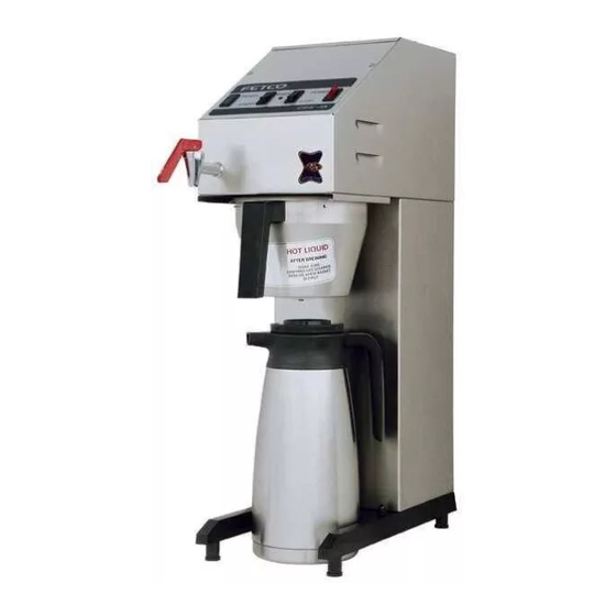
Coffee brewer and tea brewer
Hide thumbs
Also See for CBS-2018:
- User manual (16 pages) ,
- How to use (1 page) ,
- Technical bulletin (1 page)
Advertisement
Quick Links
TECHNICAL
BULLETIN
CONTROL BOARD PART # 51018
Subject:
Applies to:
CBS 18 COFFEE BREWER AND TBS 21 TEA BREWER
THE CBS 18 / TBS 21 brewer was originally manufactured
without a limit thermostat. The brewer has since been
changed and is now manufactured with a 230° F. limit
thermostat. Carefully review FIGURE 1 & 2 for proper
installation of new control board.
NOTE: This is a blow-up of the relay block located in the
upper left corner of the control board.
FIG. 2
Wiring
placement for
brewer
WITH
limit
thermostat.
FETCO ♦ 640 Heathrow Drive ♦ Lincolnshire, IL 60069 USA ♦ Tel. (800) 338-2699 or (847) 821-1177 ♦ Fax: (847) 821-1178
FIG. 1
Wiring placement for brewer
WITHOUT limit thermostat.
RED
RED
GRAY
GRAY
NUMBER
7
Date:
RED
ORANGE
Red wire from board (J12)
terminates at a fully insulated female
bullet connector. This wire will
connect to gray wire from limit
thermostat terminating at fully
insulated male bullet connector.
Red wire from board
(J13) terminates at
relay terminal # 1.
Connect remaining gray wire from
limit thermostat to terminal #2 on
relay block. Discard orange jumper
wire shipped with control board.
www.fetco.com
email : techsupport@fetco.com
October 17, 2001
Red wire from board
(J12) terminates at a fully
insulated female bullet
connector. This wire will
connect to the orange
jumper wire shipped with
this control board. The
orange jumper wire will
then connect to terminal
# 2 on relay block.
RED
Red wire from board
(J13) terminates at
relay terminal # 1.
Advertisement

Related Manuals for Fetco CBS-2018


Summary of Contents for Fetco CBS-2018
- Page 1 WITH limit thermostat. FETCO ♦ 640 Heathrow Drive ♦ Lincolnshire, IL 60069 USA ♦ Tel. (800) 338-2699 or (847) 821-1177 ♦ Fax: (847) 821-1178 NUMBER Date: ORANGE Red wire from board (J12) terminates at a fully insulated female bullet connector.
- Page 2 This board is used in both the CBS 18 and the TBS 21. When installing this board it is important that the settings on this board are properly set for the brewer it is being installed into. NOTE: Factory settings are indicated below. CBS 18 FIG.
Need help?
Do you have a question about the CBS-2018 and is the answer not in the manual?
Questions and answers