Table of Contents
Advertisement
Quick Links
Advertisement
Table of Contents

Related Manuals for D-Link DVG-7044S


Summary of Contents for D-Link DVG-7044S
- Page 1 DVG-7044S VOIP Gateway User Manual Version 1.0...
-
Page 3: Table Of Contents
Contents 1. Introduction....................3 Product Overview ............................3 Hardware Description............................ 4 2. Installation and Applications ................6 Network Interface ............................6 Gateway Assigned with a Public IP Address..................6 Gateway in a NAT network ......................... 6 Gateway assigned with a Public IP Address and serving as an IP sharing device......7 Telephone Interface Description........................ - Page 4 Backup/Restore............................57 Provision Settings............................58 System Operations (Save Settings) ......................58 Software Upgrade ............................59 Logout ................................. 59 5. IP Sharing Functions...................60 6. Coding Principle ..................63 Instruction..............................63 Dialed Number Processing Flow......................... 63 7. Advanced Feature ..................65 Static Route※ ............................. 65 RIP(Routing Information Protocol) ※......................
-
Page 5: Introduction
1. Introduction Product Overview The stand-alone VoIP Gateway carries both voice and facsimile over the IP network. It supports SIP industry standard call control protocol to be compatible with free registration services or VoIP service providers’ systems. It works in two different modes: UA (User Agent) or Server. As a standard user agent, it is compatible to all well-known Soft Switches and SIP proxy servers. -
Page 6: Hardware Description
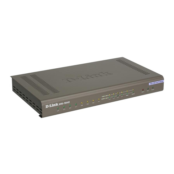
Hardware Description Front Panel Status indicators WAN, LAN indicators Voice ports indicators Power Indicator: Green light indicates a normal power supply. Run Indicator: Blinking green light indicates normal operation. Alarm Indicator: When the system starts up, the red light will blink. It also indicates the gateway’s abnormal operation. - Page 7 Rear Panel DVG-7044S Model LAN ports 1 ~ 4 FXO ports 5~8 RESET FXS ports 1 ~ 4 (built-in Ethernet switch) (PSTN line connectors) To reset the Connect LAN hosts here (telephone connectors) Connects to PSTN lines gateway to share WAN connection.
-
Page 8: Installation And Applications
2. Installation and Applications Network Interface The network interface is divided into 3 basic modes as described below: Gateway can be assigned with a Public IP Address Gateway can be built under the existing NAT Gateway can be assigned with a Public IP address and serves as an IP sharing router. Gateway Assigned with a Public IP Address The gateway will have a Public IP address for Internet connection regardless of whether it is a static IP address, DHCP (using a Cable Modem), or PPPoE (Dialup / ADSL). -
Page 9: Gateway Assigned With A Public Ip Address And Serving As An Ip Sharing Device
Gateway assigned with a Public IP Address and serving as an IP sharing device The gateway will have a Public IP address regardless of whether it is a static IP application, DHCP (using a Cable Modem), or PPPoE (To connect to your ADSL account), which can then use the functions of built-in IP sharing function to allow other PCs to be on-line at the same time. -
Page 10: Telephone Interface Description
Telephone Interface Description Example for Phone Ports: Phone Ports connecting directly to phone sets After connecting telephone sets to P1-P4, users can make direct calls, (P1-P4 are FXS interfaces). Each set acts as an independent extension line. Integrating the Phone Ports with PBX P1-P4 is FXS interfaces, and some of them can be connected to telephone sets for direct calls. -
Page 11: Example For Dvg-6004S
Example for Line Ports : Line Ports connecting directly to the Telephone Line of a PSTN P1-P4 is FXO interfaces and can all be connected to a PSTN to serve as a bridge between the PSTN and other VoIP telephones. The system also allows a call to be made from a traditional telephone line to connect with a user behind the Gateway. -
Page 12: Setting The Gateway Through Ivr
3. Setting the Gateway through IVR VoIP transmits voice data (packet) via the Internet to achieve telecommunications. This means that the telecommunication quality is closely related to the whole network environment. If any one of the telecommunicating parties has insufficient bandwidth or frequent packet loss, the telecommunication quality will be poor. - Page 13 Instructions FXS Port: When you have set the password in WEB-GUI with English character. To access GW IVR function is different. Instead of **[password]#. You should press ***[password]#. The character to number conversion can be acquired from PPPoE Character Conversion Table.
-
Page 14: Ivr Functions Table
IVR Functions Table: Function Code Description Example 111/101 WAN Port IP address Set/Query Use in conjunction with function code 114, select 1 for a Static IP 112/102 WAN Port Subnet Mask Set/Query function. 113/103 WAN Port Default Gateway Set/Query 114/104 Current Network IP Access Set/Query (1: Static IP, 2.DHCP, 3.PPPoE) 115/105... - Page 15 Function Code Description Example 211/201 Set/Query International Prefix code Prefix dialed before making an international call e.g. 002 and 005. 212/202 Set/Query Country Code Setting country code, e.g. 886 213/203 Set/Query Area Prefix Code (Long-Distance Prefix Prefix dialed before making a Code) long-distance call e.g.
-
Page 16: Ip Configuration Settings-Setting Ip Configuration Of Wan Port
IP Configuration Settings—Setting IP Configuration of WAN Port Static IP Settings NOTE: Complete static IP settings should include a static IP (Option 1 under114), IP address (111), Subnet Mask (112), and Default Gateway (113). Please contact your local Internet Service Provider (ISP) if you have any questions. -
Page 17: Recorded Voice File
ADSL PPPoE Settings NOTE: Complete PPPoE settings should include: Select PPPoE (Option 3 of 114), PPPoE account (121) and PPPoE password (122). Please contact your local Internet Service Provider (ISP) if you have any questions. Select a PPPoE After entering IVR mode, dial 114. After hearing “Enter value”, dial 3 (to select PPPoE). - Page 18 PPPoE Character Conversion Table Number Input Key Upper Case Input Key Lower Case Input Key Symbol Input Key Letter Letter ‧ " & < >...
-
Page 19: Setting A Gateway With Web Browser
4. Setting a Gateway with WEB Browser The gateway allows users to make settings using a web browser. After opening a browser, enter Gateway’s IP address as the website address in order to enter the Web configuration screen as shown in the following diagram. - Page 20 Listen Port UDP: It is not necessary to change the protocol of the communication port used by the gateway. RTP Starting Port UDP: The initial value of port number for transmitting voice data among Gateway(s). Each line requires 2 ports (RTP/RTCP). It is not necessary to change these. For example: If the starting port is 9000, then Line 1 is using 9000(RTP) and 9001(RTCP), and Line 2 is using 9002 and 9003, and so forth.
- Page 21 IP Configuration (Setting WAN Port) There are four methods of obtaining a WAN port IP address: 1. Static IP 2. DHCP, means a Dynamic IP (Cable Modem) 3. PPPoE (Dialup ADSL) 4. PPTP. Using the DHCP and PPPoE for obtaining an IP address may vary. If not familiar with the network connection, please contact your local ISP.
- Page 22 PPTP※ Select “PPTP” and enter the IP Address, Subnet mask, PPTP Server, PPTP ID and Password. Then click the “Accept” button at the bottom. BigPond (for Australia use only) Click “BigPond Cable” Enter User Name and Password. Login Server is optional. Then click the “Accept” button at the bottom.
- Page 23 Some Internet Service Providers (ISP) assigns the bandwidth via the MAC (Media Access Control) Address. You can click the " Clone" button to copy the MAC address of the Ethernet Card installed in the computer used to configure the device. It is only necessary to fill in the field if required by your ISP. The “Your MAC Address”...
-
Page 25: Network Settings (Lan)
Network Settings (LAN) LAN interface mode※ Router: The system serves as a router with NAT. Bridge: The system serves as a bridge between WAN port and LAN port without NAT. (LAN default gateway will still be accessible for configuration). LAN IP/Subnet mask Gateway LAN Port IP address and the subnet mask value. - Page 26 port IP address, (e.g. setting the IP address to 192.168.99.254.) DHCP Settings Enable DHCP Server: Enable or Disable DHCP server service of gateway. IP Pool Starting Address: The first IP address to be assigned to DHCP clients. IP Pool ending Address: The last IP address to be assigned to DHCP clients. Lease Time: The valid period of an assigned IP address.
-
Page 27: Qos Settings
QoS Settings WAN QoS QoS (Quality of Service): Sets an external bandwidth to ensure sound quality during transmission (When this function is enabled, the voice packet has the highest priority to ensure telecommunication quality while less bandwidth is assigned for data transmission). Some models of the gateway without this function can adjust the bandwidth automatically. -
Page 28: Nat/Ddns
NAT/DDNS NAT Traversal If a Gateway is set up under an IP sharing setting, you can select either the NAT or STUN protocol. NAT Public IP: The IP address used by the gateway should be a virtual address. Further more, users must set the Virtual Server Mapping in the NAT Server (A virtual server is defined as a Service Port, and all requests to this port will be redirected to this specified the server IP address). - Page 29 DDNS...
-
Page 30: Telephony Settings
These settings are only necessary when the gateway is set up under a NAT that uses a dynamic IP address and do not support DDNS. Choose a DDNS Server: The current system allows users to choose either DynDNS、TZO、3322.org、 PeanutHull or a private server. Please apply for a user account before choosing a service provider. Server address: Sets up the IP address or URL (Uniform Resource Locator) of the DDNS Server. - Page 31 FXS Caller ID Generation: Select this option to enable the caller ID display function. When enabled, the caller’s phone number will be displayed on your phone set when the call comes through. FSK is preferred in some countries. FXO Caller ID Detection: To detect the Caller ID delivered from PSTN to the FXO port. While enabled, the Caller ID detected on the FXO port will be send to the SIP Proxy Server on dialing out calls.
- Page 32 2. The assigned hotline for DVG-7044S L2 is 702 and the wait time is 0 second. When L2 receives a call from an outside line, it will be automatically diverted to extension 702.
- Page 33 Trunk Hunting Order: To set FXO dial-out mode when there is an incoming call dialed FXO representative number. First Idle: The gateway will assign each unassigned call from first FXO line. Sequential: The gateway will automatically assign the first unassigned call to the first FXO line.
- Page 34 Force Calling Thru PSTN code: Dial the code to get a PSTN line for dial out. For example: If you would like dial “23456789” through PSTN and Force Calling Thru PSTN code is *33, just dial “*33 23456789” Early Media Treatment: If it is disabled, the system will send RTP immediately when the connection with Proxy is set up.
-
Page 35: Sip
All Call through OutBound Proxy:An outbound proxy server handles SIP call signaling as a standard SIP proxy server would. Furthermore, it receives and transmits phone conversation traffic (media) in between two talking gateways. This option tells the gateway to send and receive all SIP packets to the destined outbound proxy server rather than the remote gateway. - Page 37 E.164 International Call Prefix Digit: Enter the International call prefix. Country Code: Users please select the desired country code. Long Distance Call prefix Digit: The long-distance prefix digit for making a long-distance call. Area Code: Please enter the area code. E.164 Numbering: To invite Proxy to follow the E.164 rule.
- Page 38 Enable Support of SIP Proxy Server / Soft Switch: Enable the functions to inter-work with Proxy Server / Soft Switch. When SIP Proxy 1 and 2 are enabled, the system will register to SIP Proxy 2 after all lines are failed to register to SIP Proxy 1. SIP Proxy 2 is a backup system.
- Page 39 Proxy. Register: Register to Proxy if ticked. Invite with ID / Account: DVG-7044S can be invited to a VoIP trunk gateway w/o register to a Proxy. Please contact your ITSP NOTE: Please ensure that if Proxy Server allows one account for many ports using before using representative number to register.
-
Page 40: Calling Features
Calling Features Do Not Disturb: It will only be able to call out when it is enabled. Unconditional Forward: All incoming calls will be forwarded to the “Forwarding Number” automatically. If it forwards to FXO, it only make FXO hook off, not make FXO dial out. Busy Forward: Forward the incoming call to “Forwarding Number”... - Page 41 Calling Feature Instructions: Call Hold: Ongoing call will be put on hold after FLASH button pressed on the phone set. The gateway will play a repeating music to the remote end. Call Transfer: Ongoing call will be put on hold after FLASH button pressed on local phone set (gateway plays a repeating music to the remote end).
-
Page 42: Advanced Options
Advanced Options There are two levels to enter Web. Administrator is able to change all settings. Web UI only changes some settings. NOTE: Enter new Login ID and password for two levels. Web UI auto log out: When logging in a web page, if a user does not act within the effective time range, the user will be disconnected from the web page to allow others to login. -
Page 43: Line Settings
Enable Out-of-Band DTMF: To send DTMF keys (0~9, *, #,) follow the RFC2833 rules or via SIP Info. Enable Hook Flash Event: The gateway will deliver the flash signal to remote party via RFC2833 or SIP Info. Payload Type:Payload type of RFC2833. Uses Second CPT for VoIP Call: This function is usually applied when the user selects VoIP as the primary path for outgoing calls and PSTN as the backup. -
Page 44: Codec
answer the call. ※ Codec Preferred Codec Type: Since different voice codec have different compression ratios, so the sound quality and occupied bandwidths are also different. It is recommended to use the default provided (G.723.1) because it occupies less bandwidth and will provide better sound quality. - Page 45 Enable Secure T.38: This allows gateways to send faxes on both sides. T.30: The system uses T.30 as the protocol for fax transmission. The parameter settings are the same as for voice transmission. However, enabling the fax function will consume more network resources and will affect transmission quality.
-
Page 46: Digit Map
Digit Map There are 50 sets of leading digit entries to choose voice routing interface – Auto select, PSTN or VoIP. Default Call Route: The default call route can be Auto, VoIP, PSTN and Deny. Auto (VoIP first): The call route is VoIP first, and the next is PSTN. VoIP: The call route is VoIP only. -
Page 47: Phone Book
Phone Book This system can set up and store 100 phone numbers into a phone book and provides an IP address query when calling to other gateway(s). If no Phone books manager is set within a gateway group, then all Gateway systems have to set up phone data for each the gateway to communicate with each other. -
Page 48: Caller Filter
Caller Filter This function is used at allow or deny SIP Invite from the Proxy list ONLY. Filter IP Address: Fill up with the start IP you would like to allow/deny. Subnet mask: Fill up with the subnet mask you would like to allow/deny. ACL for Management You can use ACL to allow the user that is from some IP address to enter Web. -
Page 49: Language
Language The system provides English, Traditional Chinese, and Simplified Chinese to display text on Web pages. Meanwhile, it will change the language for IVR (Interactive Voice Response). Transit Call Control If you wish to restrict a general user (one who is not required to enter the PIN code) to local calls only and prohibit him/her from making long-distance calls started with a prefix “0”, do the following steps: Enable the Outbound Call Control function, Set the PIN code for Outbound Level 5 to blank,... -
Page 50: Long-Distance Control Table
Long-Distance Control Table This table controls the level of authority of an outgoing call through FXO. If Level 0 (the highest level) is set to prohibit dialing any number started with prefix 0204, then any level below 0 (including Levels 1 to 5) is also prohibited. If Level 1 is set to prohibit dialing any number with prefix 0, then any level below 1 (including Levels 2 to 5) is also prohibited. -
Page 51: Cpt/Cadence Settings
CPT/Cadence Settings CPT/Cadence setting parameters serve as the basis of an FXO interface to determine whether or not a PSTN-call receiving party has hung up the phone. If the following parameters differ from the parameters of the actual assigned lines, it could cause the FXO to continue to engage a line. Busy Tone Cadence Measurement Busy Tone Cadence Measurement: Provide a best solution of FXO integrated with PSTN or PBX. - Page 52 NOTE: To cope with different local PSTN and different PBX models, the system provides CPT Auto Detect function to prevent the FXO from engaging a line. However, if the line of the receiving party is engaged and his/her PSTN uses a voice prompt to replace the traditional beep sound, then the system would not be able to detect a busy tone.
- Page 53 Direct Connection to PSTN 36008913 36008914 Connect one of the trunk lines to the Gateway FXO Port (For MODEL 2S2O, please connect to P3). The line of “Dial Number” (36008913) must be hook on. Detect Channel: Enter 3 (The trunk line is connected to P3, and uses P3 for outgoing detection).
- Page 54 Connected to a PBX Extension Line If the gateway is connected to a PBX extension line, then the busy tone of both the PBX and the PSTN must be detected. Connecting to a PBX extension line and detecting the busy tone of the PBX 36008913 Connect one of the PBX extension lines to the Gateway FXO Port (For MODEL 2S2O, connect the line to P3).
- Page 55 Detection in Progress: during detection, the following windows will appear. Once detection of a busy tone is in progress, the system will dial the number to be tested (in this case 36008913). After it rings pick up the phone and enter”#”, then hang up. The system will then detect a busy tone automatically.
-
Page 56: Save Settings
Filling in the CPT Table Fill in the table after the detection is completed as below, where the values are the frequency and On-and-Off ratio detected. Please click the “Accept” button. If connecting Gateway to a PBX extension line, please do not set the detected busy tone of the PBX and the PSTN in the same set, otherwise the value detected the first time will be overwritten. -
Page 57: System Information
System Information This page shows that the status of VoIP Gateway. There are Port Status, Server Registration Status, WAN Port Information, LAN Port Information and Hardware. Port Status: It includes if each port registers to Proxy successfully, the lasted dialed number, how many calls each port had since the system is start, etc. -
Page 58: Rtp Packet Summary
RTP Packet Summary Displays the information of the last finished call. It contains peer IP, peer port, packets sent, packet received and packet lost. Press the button of Refresh to get the latest RTP Packet Summary. STUN Inquiry Use STUN Inquiry to know what NAT type of the router. Ping Test Use “ping”... -
Page 59: Snmp
SNMP Enable SNMP Agent: Enable SNMP if ticked. Get/Set/Trap Community: Enter Community name to Read, Write and Trap. Trap Host: Enter the IP of Trap Host. This is the time setting. After the gateway is on the Internet, it will set its watch with Time Server. Time Zone: Set the Time Zone where the gateway resides. -
Page 60: Provision Settings
Provision Settings Fill in the parameters needed of Provision Server from your provider. System Operations (Save Settings) Some settings are effective by Restart. Remember to save all settings by Save Settings before to restart. Save Settings: Save settings after completing. The new settings will take effect after the system is restarted. -
Page 61: Software Upgrade
Software Upgrade Gateway provides software upgrade function for a remote end. Your provider gives all parameters. Upgrade Server: Choose the server type of your provider. Software Upgrade Server IP: Enter the software server IP address. Software Upgrade Server Port: Enter the port that server uses. TFTP is 69, and FTP is 21. -
Page 62: Ip Sharing Functions
5. IP Sharing Functions All Gateway series have a built-in IP sharing function. The settings and instructions at a PC end are described below: Current Intranet only supports static IP mode, and the settings at the PC end are as follow: Available IP address Range : 192.168.8.1 –... - Page 63 The IP settings on PC are as follows (using Windows 2000 for example) Open Start->Settings->Control Panel Open Network and Dial-up Connection Open Local Area Connection Click Properties...
- Page 64 Select TCP/IP, and then click Properties. Select “Use the following IP Address ” and enter IP address, Subnet Mask, and Default Gateway. Please note that an IP address in the same domain cannot be reused. Then, enter the DNS server IP address (varies in different networks.
-
Page 65: Coding Principle
6. Coding Principle Instruction After a phone number is entered, dial # to call out immediately or, wait until the “Inter DTMF Timeout” expires (defined in “Advanced Options”, default=4 seconds). If the phone number fits the setting of Digit Map, the gateway dials out the phone number through the assigned interface automatically. - Page 66 Start Enter a phone number (D#) Is (D#) Dial the number defined in Speed defined in Dial table? SpeedDial table Is (D#) defined in Extension table? Is (D#) defined in Phonebook table? Is (D#) defined in Phonebook Manager? Is (D#) defined in SIP proxy server? Dial out as defined...
-
Page 67: Advanced Feature
7. Advanced Feature Static Route※ Build static routes within an internal network. These routes will not apply to the Internet. Route: Enter the IP of the specified network. Route Mask: Enter the subnet mask to be used for the specified network. Next Hop IP: Enter the IP address to the specified network. -
Page 68: Port Filtering
Port filtering Port filtering enables you to control all data that can be transmitted in routers; principles of filtering---When the port used at the source end is within the limited scope, it will be filtered without transmission. Enable port filtering: whether to enable this function or not. Port Range: Set the range of port to be filtered, suppose it is 80 and when use protocol is Both or TCP, all computers will be unable to use the services of http (port 80)—... -
Page 69: Mac Filtering
MAC Filtering MAC (Media Access Control) address filtering is to filter the transmission of data by network card physical address. MAC: input MAC that will limit accessing Internet PC. Virtual Server Enabling the users on Internet to access the WWW, FTP and other services under your NAT. When remote user are accessing Web or FTP servers through WAN end IP address, it will be routed to the server at the internal LAN end and be routed to the server at the internal LAN end as appropriate in accordance with the externally required services... -
Page 70: Url Filter
URL Filter※ URL filter is used to deny device from LAN accessing specific web sites. The system will block the URL that contains the string. Special Applications※ Provide multiple connections for special applications. Name: The name of the special application. Incoming Type: The protocol used to trigger the special application. -
Page 71: Dos Prevention Settings
DoS Prevention Settings※ Enable DoS Prevention: To prevent DoS from WAN. Enable DoS Prevention on LAN: To prevent DoS from LAN. Enable Source IP Blocking: Block the IP. Blocking Time: The time to block the IP.
Need help?
Do you have a question about the DVG-7044S and is the answer not in the manual?
Questions and answers