Sign In
Upload
Manuals
Brands
Pfeiffer Vacuum Manuals
Water Pump
HEPTA 650 L
Pfeiffer Vacuum HEPTA 650 L Manuals
Manuals and User Guides for Pfeiffer Vacuum HEPTA 650 L. We have
2
Pfeiffer Vacuum HEPTA 650 L manuals available for free PDF download: Operating Instructions Manual
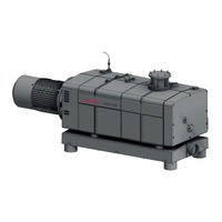
Pfeiffer Vacuum HEPTA 650 L Operating Instructions Manual (108 pages)
Screw pump
Brand:
Pfeiffer Vacuum
| Category:
Water Pump
| Size: 11 MB
Table of Contents
Deutsch
3
Table of Contents
3
Zu dieser Anleitung
7
Gültigkeit
7
Mitgeltende Dokumente
7
Varianten
7
Zielgruppe
7
Konventionen
7
Anweisungen IM Text
7
Piktogramme
8
Aufkleber auf dem Produkt
8
Abkürzungen
9
Abb. 1: Position der Aufkleber auf der Schraubenpumpe
9
Sicherheitshinweise
10
Allgemeine Sicherheitshinweise
10
Sicherheit
10
Sicherheitsmaßnahmen
13
Einsatzgrenzen des Produkts
13
Bestimmungsgemäße Verwendung
14
Vorhersehbarer Fehlgebrauch
14
Personenqualifikation
14
Personenqualifikation Sicherstellen
14
Personenqualifikation bei Wartung und Reparatur
15
Produktbeschreibung
16
Funktion
16
Abb. 2: Funktionsprinzip
16
Abb. 3: Aufbau der Schraubenpumpe
16
Produkt Identifizieren
17
Lieferumfang
17
Produktmerkmale
17
Gasballast
17
Schalldämpfung
17
Sperrgassystem
17
Wasserkühlung
17
Temperaturüberwachung
17
Transport und Lagerung
18
Transport
18
Lagerung
19
Abb. 4: Vakuumpumpe Transportieren
19
Installation
20
Vakuumpumpe Aufstellen
20
Vakuumseite Anschließen
20
Auspuffseite Anschließen
21
Abb. 5: Auspuffseite Anschließen
22
Kühlwasserversorgung Anschließen
22
Abb. 6: Kühlwasseranschluss
23
Sperrgas Anschließen
24
Abb. 7: Sperrgasanschluss
24
Schmiermittel Einfüllen
25
Schmiermittel auf der Motorseite Einfüllen
25
Abb. 8: Schmiermittel auf der Motorseite Einfüllen
25
Schmiermittel auf der Vakuumseite Einfüllen
26
Netzanschluss Herstellen
26
Abb. 9: Schmiermittel auf der Vakuumseite Einfüllen
26
Dreiphasenmotor mit 6-Poliger Klemmenplatte Anschließen
27
Abb. 10: Dreieckschaltung
27
Abb. 13: Dreieckschaltung
28
Abb. 14: Sternschaltung
28
Dreiphasenmotor mit 12-Poliger Klemmenplatte Anschließen
28
Abb. 12: Doppelsternschaltung
28
Abb. 11: Sternschaltung
28
Drehrichtung Prüfen
29
Kaltleiterauslösegerät Anschließen
29
Abb. 15: Drehrichtung Prüfen
29
Abb. 16: Anschlussbeispiel mit Kaltleiterauslösegerät
30
Betrieb
31
Vakuumpumpe in Betrieb Nehmen
31
Vakuumpumpe Einschalten
31
Vakuumpumpe Ausschalten
32
Wartung
33
Wartungsinformationen
33
Checkliste für Inspektion und Wartung
34
Schmiermittelstand Kontrollieren
35
Schmiermittel Wechseln
35
Abb. 17: Schmiermittelstand Kontrollieren
35
Schmiermittel auf der Motorseite Ablassen
36
Abb. 18: Schmiermittel auf der Motorseite Ablassen
36
Schmiermittel auf der Vakuumseite Ablassen
37
Schmiermittel auf der Motorseite Einfüllen
37
Abb. 19: Schmiermittel auf der Vakuumseite Ablassen
37
Abb. 20: Schmiermittel auf der Motorseite Einfüllen
37
Schmiermittel auf der Vakuumseite Einfüllen
38
Saugsieb Reinigen
38
Abb. 21: Schmiermittel auf der Vakuumseite Einfüllen
38
Abb. 22: Saugsieb Demontieren und Montieren
39
Gasballastfilter Reinigen
39
Abb. 23: Gasballastfilter Reinigen
40
Außerbetriebnahme
41
Vakuumpumpe Außer Betrieb Nehmen
41
Wiederinbetriebnahme
41
Recycling und Entsorgung
43
Allgemeine Entsorgungshinweise
43
Schraubenpumpe Entsorgen
43
Störungen
44
Servicelösungen von Pfeiffer Vacuum
46
Zubehör Bestellen
48
Verbrauchsmaterialien
48
Zubehörinformationen
48
Zubehör
48
Technische Daten und Abmessungen
49
Allgemeines
49
Technische Daten
49
Medienberührende Werkstoffe
49
Abmessungen
50
Abb. 24: Abmessungen Hepta 450 L
50
Abb. 25: Abmessungen Hepta 650 L (ISO-F DN100)
51
Abb. 26: Hepta 650 L (ISO-F DN160)
51
Konformitätserklärung
52
Konformitätserklärung
53
English
55
About this Manual
59
Applicable Documents
59
Conventions
59
Instructions in the Text
59
Target Group
59
Validity
59
Variants
59
Pictographs
60
Stickers on the Product
60
Tbl. 1: Stickers on the Product
60
Abbreviations
61
Fig. 1: Position of the Stickers on the Screw Pump
61
Tbl. 2: Abbreviations Used in this Document
61
General Safety Information
62
Safety
62
Safety Instructions
62
Limits of Use of the Product
65
Safety Precautions
65
Ensuring Personnel Qualification
66
Foreseeable Improper Use
66
Personnel Qualification
66
Proper Use
66
Tbl. 3: Limits of Use of the Product
66
Personnel Qualification for Maintenance and Repair
67
Fig. 2: Operating Principle
68
Fig. 3: Arrangement of Screw Pump
68
Function
68
Product Description
68
Gas Ballast
69
Identifying the Product
69
Product Features
69
Scope of Delivery
69
Sealing Gas System
69
Silencer
69
Temperature Monitoring
69
Water Cooling
69
Transport
70
Transportation and Storage
70
Bearing
71
Fig. 4: Transporting the Vacuum Pump
71
Connecting the Vacuum Side
72
Installation
72
Setting up the Vacuum Pump
72
Connecting the Exhaust Side
73
Tbl. 5: Maximum Permissible Forces on the Intake Flange
73
Connecting the Cooling Water Supply
74
Fig. 5: Connecting the Exhaust Side
74
Fig. 6: Cooling Water Connection
74
Connecting Sealing Gas
75
Tbl. 6: Requirements on the Cooling Water Composition
75
Tbl. 7: Prerequisites for the Cooling Water
75
Tbl. 8: Select Diameter of the Orifice Plate
75
Fig. 7: Sealing Gas Connection
76
Filling with Lubricant
76
Tbl. 9: Requirements for the Sealing Gas
76
Fig. 8: Filling up Lubricant on the Motor Side
77
Fig. 9: Filling up Lubricant on the Vacuum Side
77
Filling up Lubricant on the Motor Side
77
Filling up Lubricant on the Vacuum Side
77
Connect to Mains Power Supply
78
Connect Three Phase Motor with 12-Pin Terminal Board
79
Connect Three Phase Motor with 6-Pin Terminal Board
79
Fig. 10: Delta Connection
79
Fig. 11: Star Circuit
79
Fig. 12: Double Star Circuit
79
Checking the Direction of Rotation
80
Fig. 13: Delta Connection
80
Fig. 14: Star Circuit
80
Fig. 15: Checking the Direction of Rotation
80
Connecting the PTC Thermistor Tripping Unit
81
Fig. 16: Connection Example with PTC Thermistor Tripping Unit
81
Commissioning Vacuum Pump
82
Operation
82
Switching on the Vacuum Pump
82
Switching off the Vacuum Pump
83
Maintenance
84
Maintenance Information
84
Checklist for Inspection and Maintenance
85
Changing Lubricant
86
Checking the Lubricant Level
86
Fig. 17: Checking the Lubricant Level
86
Draining Lubricant on the Motor Side
87
Fig. 18: Draining Lubricant on the Motor Side
87
Draining Lubricant on the Vacuum Side
88
Fig. 19: Draining Lubricant on the Vacuum Side
88
Fig. 20: Filling up Lubricant on the Motor Side
88
Filling up Lubricant on the Motor Side
88
Cleaning the Intake Strainer
89
Fig. 21: Filling up Lubricant on the Vacuum Side
89
Filling up Lubricant on the Vacuum Side
89
Cleaning the Gas Ballast Filter
90
Fig. 22: Disassembling and Cleaning the Intake Strainer
90
Fig. 23: Cleaning the Gas Ballast Filter
91
Decommissioning
92
Decommissioning the Vacuum Pump
92
Recommissioning
92
Disposing of the Screw Pump
94
General Disposal Information
94
Recycling and Disposal
94
Malfunctions
95
Tbl. 11: Troubleshooting
96
Service Solutions by Pfeiffer Vacuum
97
Accessories
99
Accessory Information
99
Consumables
99
Ordering Accessories
99
General
100
Substances in Contact with the Media
100
Technical Data
100
Technical Data and Dimensions
100
Dimensions
101
Fig. 24: Dimensions of Hepta 450 L
101
Tbl. 17: Materials that Make Contact with the Process Media
101
Fig. 25: Dimensions of Hepta 650 L (ISO-F DN100)
102
Fig. 26: Hepta 650 L (ISO-F DN160)
102
Declaration of Conformity
103
Declaration of Conformity
104
Advertisement
Pfeiffer Vacuum HEPTA 650 L Operating Instructions Manual (52 pages)
Screw pump
Brand:
Pfeiffer Vacuum
| Category:
Water Pump
| Size: 5 MB
Table of Contents
Table of Contents
3
1 About this Manual
7
Validity
7
Applicable Documents
7
Variants
7
Target Group
7
Conventions
7
Instructions in the Text
7
Pictographs
8
Stickers on the Product
8
Tbl. 1: Stickers on the Product
8
Abbreviations
9
Tbl. 2: Abbreviations Used in this Document
9
Fig. 1: Position of the Stickers on the Screw Pump
9
2 Safety
10
General Safety Information
10
Safety Instructions
10
Safety Precautions
13
Limits of Use of the Product
13
Proper Use
14
Foreseeable Misuse
14
Personnel Qualification
14
Ensuring Personnel Qualification
14
Tbl. 3: Limits of Use of the Product
14
Personnel Qualification for Maintenance and Repair
15
3 Product Description
16
Function
16
Fig. 2: Operating Principle
16
Fig. 3: Arrangement of Screw Pump
16
Water Cooling
17
Temperature Monitoring
17
Gas Ballast
17
Sealing Gas System
17
Silencer
17
Identifying the Product
17
Product Features
17
Scope of Delivery
17
4 Transportation and Storage
18
Transport
18
Storage
19
Fig. 4: Transporting the Vacuum Pump
19
5 Installation
20
Setting up the Vacuum Pump
20
Connecting the Vacuum Side
20
Connecting the Exhaust Side
21
Fig. 5: Connecting the Exhaust Side
21
Connecting the Cooling Water Supply
22
Fig. 6: Cooling Water Connection
22
Connecting Sealing Gas
23
Fig. 7: Sealing Gas Connection
23
Fill Lubricant
24
Tbl. 8: Requirements for the Sealing Gas
24
Filling up Lubricant on the Motor Side
25
Filling up Lubricant on the Vacuum Side
25
Fig. 8: Filling up Lubricant on the Motor Side
25
Fig. 9: Filling up Lubricant on the Vacuum Side
25
Connect to Mains Power Supply
26
Connect Three Phase Motor with 6-Pin Terminal Board
26
Connect Three Phase Motor with 12-Pin Terminal Board
27
Fig. 10: Delta Connection
27
Fig. 11: Star Circuit
27
Fig. 12: Double Star Circuit
27
Fig. 13: Delta Connection
27
Checking the Direction of Rotation
28
Connecting the PTC Thermistor Tripping Unit
28
Fig. 14: Star Circuit
28
Fig. 15: Checking the Direction of Rotation
28
Fig. 16: Connection Example with PTC Thermistor Tripping Unit
29
6 Operation
30
Commissioning the Vacuum Pump
30
Switching on the Vacuum Pump
30
Switching off the Vacuum Pump
31
7 Maintenance
32
Maintenance Information
32
Checklist for Inspection and Maintenance
33
Checking the Lubricant Level
34
Changing the Lubricant
34
Fig. 17: Checking the Lubricant Level
34
Draining Lubricant on the Motor Side
35
Fig. 18: Draining Lubricant on the Motor Side
35
Draining Lubricant on the Vacuum Side
36
Filling up Lubricant on the Motor Side
36
Fig. 19: Draining Lubricant on the Vacuum Side
36
Fig. 20: Filling up Lubricant on the Motor Side
36
Filling up Lubricant on the Vacuum Side
37
Cleaning the Intake Strainer
37
Fig. 21: Filling up Lubricant on the Vacuum Side
37
Cleaning the Gas Ballast Filter
38
Fig. 22: Disassembling and Cleaning the Intake Strainer
38
Fig. 23: Cleaning the Gas Ballast Filter
39
8 Decommissioning
40
Decommissioning the Vacuum Pump
40
Recommissioning
40
9 Recycling and Disposal
42
General Disposal Information
42
Disposing of the Screw Pump
42
10 Malfunctions
43
Tbl. 10: Troubleshooting
44
11 Service Solutions by Pfeiffer Vacuum
45
12 Accessories
47
Accessory Information
47
Ordering Accessories
47
Consumables
47
13 Technical Data and Dimensions
48
General
48
Technical Data
48
Substances in Contact with the Media
48
Dimensions
49
Tbl. 16: Materials that Make Contact with the Process Media
49
Fig. 24: Dimensions of Hepta 450 L
49
Fig. 25: Dimensions of Hepta 650 L (ISO-F DN100)
50
Fig. 26: Hepta 650 L (ISO-F DN160)
50
Declaration of Conformity
51
Advertisement
Related Products
Pfeiffer Vacuum HEPTA 630 P
Pfeiffer Vacuum HEPTA 100 P
Pfeiffer Vacuum HEPTA 200 P
Pfeiffer Vacuum HEPTA 300 P
Pfeiffer Vacuum HEPTA 950 L
Pfeiffer Vacuum HEPTA 450 L
Pfeiffer Vacuum HEPTA 400 P
Pfeiffer Vacuum HENA 300
Pfeiffer Vacuum HENA 50
Pfeiffer Vacuum HENA 101
Pfeiffer Vacuum Categories
Water Pump
Control Unit
Measuring Instruments
Industrial Equipment
Security Sensors
More Pfeiffer Vacuum Manuals
Login
Sign In
OR
Sign in with Facebook
Sign in with Google
Upload manual
Upload from disk
Upload from URL