
Related Manuals for Pfeiffer Vacuum HENA 201 R


Summary of Contents for Pfeiffer Vacuum HENA 201 R
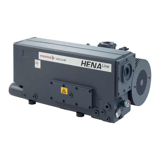
- Page 1 OPERATING INSTRUCTIONS Translation of the Original HENA 201 R | 251 | 301 R Rotary vane pump...
- Page 2 Dear Customer, Thank you for choosing a Pfeiffer Vacuum product. Your new rotary vane pump is designed to support you by its performance, its perfect operation and without interfering your individual application. The name Pfeiffer Vacuum stands for high-quality vacuum technology, a comprehensive and complete range of top-quality products and first-class service.
-
Page 3: Table Of Contents
Table of contents Table of contents About this manual Validity 1.1.1 Applicable documents 1.1.2 Variants Target group Conventions 1.3.1 Instructions in the text 1.3.2 Pictographs 1.3.3 Stickers on the product 1.3.4 Abbreviations Trademark proof Safety General safety information Safety instructions Safety precautions Limits of use of the product Proper use... - Page 4 Recommissioning Recycling and disposal General disposal information Dispose of rotary vane pump Malfunctions Service solutions by Pfeiffer Vacuum Spare parts 12.1 Ordering spare part packages 12.2 Operating fluids – Maintenance level 1 12.3 Maintenance kit – maintenance level 1 12.4 Overhaul kit – maintenance level 3 12.5 Set of seals...
- Page 5 Conversion table: Units for gas throughput Tbl. 18: Technical data for Hena 201 R | 301 R with operating fluid D1 Tbl. 19: Technical data for Hena 201 R | Hena 251 | 301 R with operating fluid P3 5/62...
- Page 6 Dismantling / assembling the intake strainer Fig. 21: Changing the gas ballast filter Fig. 22: Dimensions Hena 201 R | Three phase motor IE3 Fig. 23: Dimensions Hena 251 | Three phase motor IE3 Fig. 24: Dimensions Hena 301 R | Three phase motor IE3 Fig.
-
Page 7: About This Manual
Keep the manual for future consultation. 1.1 Validity This operating instructions is a customer document of Pfeiffer Vacuum. The operating instructions de- scribe the functions of the named product and provide the most important information for the safe use of the device. The description is written in accordance with the valid directives. The information in this op- erating instructions refers to the product's current development status. -
Page 8: Pictographs
2020 D-35614 Asslar Rating plate of the rotary vane vacuum pump Made in Germany Vacuum Pump = DEM119400160 Hena 201 R Motor rating plate (not shown) = 1 hPa (mbar) = 360 m = 1800 min = 227 kg = P3 Oil quantity = 6.5 L... -
Page 9: Abbreviations
About this manual 1.3.4 Abbreviations Abbreviation Meaning in this document Operating instructions N.N. Mean sea level Earthed conductor (protective earth) Width across flats RSSR Radial shaft seal ring Tbl. 2: Abbreviations used in this document 1.4 Trademark proof ● Loctite ® is a trademark of HENKEL IP & HOLDING GMBH. 9/62... -
Page 10: Safety
Safety 2 Safety 2.1 General safety information The following 4 risk levels and 1 information level are taken into account in this document. DANGER Immediately pending danger Indicates an immediately pending danger that will result in death or serious injury if not observed. ►... - Page 11 Safety Risks during installation DANGER Danger to life from electric shock Touching exposed and voltage-bearing elements causes an electric shock. Improper connection of the mains supply leads to the risk of touchable live housing parts. There is a risk to life. ►...
- Page 12 Safety Risks during operation WARNING Danger of poisoning due to toxic process media escaping from the exhaust pipe During operation with no exhaust line, the vacuum pump allows exhaust gases and vapors to escape freely into the air. There is a risk of injury and fatality due to poisoning in processes with toxic process media.
- Page 13 Safety Risks during maintenance, decommissioning and malfunctions WARNING Health hazard through poisoning from toxic contaminated components or devices Toxic process media result in contamination of devices or parts of them. During maintenance work, there is a risk to health from contact with these poisonous substances. Illegal disposal of toxic sub- stances causes environmental damage.
-
Page 14: Safety Precautions
Safety CAUTION Scalding from hot operating fluid Danger of burns when draining operating fluid if it comes into contact with the skin. ► Wear protective equipment. ► Use a suitable collection receptacle. CAUTION Danger of burns on hot surfaces In the event of a fault, the surface temperature of the vacuum pump can increase to above 105 °C. ►... -
Page 15: Limits Of Use Of The Product
(F4, F5, A113) as operating fluid. ► Adhere to the installation, commissioning, operating, and maintenance instructions. ► Do not use any accessory parts other than those recommended by Pfeiffer Vacuum. 2.6 Foreseeable improper use Improper use of the product invalidates all warranty and liability claims. Any use that is counter to the purpose of the product, whether intentional or unintentional, is regarded as misuse, in particular: ●... -
Page 16: Personnel Qualification
● Use of accessories or spare parts not listed in these operating instructions ● Use of operating fluids other than those specified by Pfeiffer Vacuum ● Use of D1 or mineral oil as operating fluid with an oxygen concentration level of > 21 %. Mineral oils are combustible and ignite in high temperatures and when they come into contact with pure oxygen. -
Page 17: Product Description
Product description 3 Product description 3.1 Function The rotary vane pumps of the HenaLine are single-stage, oil-sealed rotary positive displacement pumps with air cooling and circulatory lubrication. A non-return valve in the vacuum connection closes the in- take line automatically when the rotary vane pump is switched off and prevents an operating fluid return flow. -
Page 18: Cooling
The rotary vane pump is cooled by thermal radiation from its surface, the air current from the two fans and the pumped gas. In case of thermally unfavorable ambient conditions, Pfeiffer Vacuum recommends the use of a pump version with oil/water heat exchanger. - Page 19 Product description ● Locking caps for vacuum and exhaust connection ● Operating instructions 19/62...
-
Page 20: Transportation And Storage
► Always transport the vacuum pump horizontally or without operating fluid filling. ► Fill in the operating fluid only at the final installation location. Preparations for transport Pfeiffer Vacuum recommends keeping the transport packaging and original protective cov- General information regarding safe transport 1. Observe the weight specified on packaging. -
Page 21: Storing The Vacuum Pump
5. Always place the vacuum pump on an adequately sized, level surface. 4.2 Storing the vacuum pump Storage Pfeiffer Vacuum recommends storing the products in their original transport packaging. Procedure 1. Seal the vacuum and exhaust connection. 2. Make sure that the gas ballast valve is closed. -
Page 22: Installation
Property damage from contaminated gases Pumping down gases that contain impurities (condensate, particles) damages the vacuum pump. ► Use suitable filters or separators from the Pfeiffer Vacuum range of accessories, to protect the vacuum pump. Installation and operation of accessories Pfeiffer Vacuum offers a series of special, compatible accessories for its rotary vane pumps. -
Page 23: Connecting The Exhaust Side
Shop. 7. Support or suspend the piping to the vacuum pump so that no piping system forces act on the vacuum pump. 8. Use a screwing flange, separator or filter from the Pfeiffer Vacuum line of accessories if necessa- 5.3 Connecting the exhaust side... -
Page 24: Filling The Operating Fluid
Vacuum are also excluded. ► Only use approved operating fluids. ► Only use other application-specific operating fluids after consultation with Pfeiffer Vacuum. The type of operating fluid specified, as well as the filling quantity for the entire rotary vane vacuum pump, are shown on the rating plate. -
Page 25: Connecting The Oil/Water Heat Exchanger
Installation 4. Seal the vacuum connection. 5. Start the vacuum pump. 6. Operate the vacuum pump for approx. 5 minutes. 7. Switch off the vacuum pump. 8. Wait approx. 1 minute until the operating fluid has accumulated in the operating fluid separator. 9. -
Page 26: Establishing Mains Connection
Installation Fig. 7: Cooling water connection 1 Cooling water outlet Oil/water heat exchanger 2 Cooling water inlet Making the cooling water connection 1. Connect the cooling water lines: – Cooling water inlet – Cooling water outlet 2. Ensure that the cooling water outlet is unpressurized. 3. -
Page 27: Connect Three Phase Motor With 6-Pin Terminal Board
► Route the mains connection in accordance with locally applicable provisions. ► Always provide a suitable mains fuse to protect the motor and supply cable in the event of a fault. – Pfeiffer Vacuum recommends the circuit breaker type "K" with slow tripping characteristic. NOTICE Property damage from high starting torque The specific load behavior of the vacuum pump requires direct on-line starting at full motor power. -
Page 28: Checking The Direction Of Rotation
Installation Fig. 10: Double star circuit Connect the three phase motor with double star circuit ► Connect the three phase motor according to the connection diagram. Fig. 11: Delta connection Connect the three phase motor with delta connection ► Connect the three phase motor according to the connection diagram. Fig. -
Page 29: Frequency Inverter For Vacuum Pumps With 3-Phase Motor
20.9 380 – 400 12.1 25.6 24.2 24.2 12.1 12.1 Tbl. 6: Motor protection switch settings for global motor Hena 201 R Voltage [V] Frequency [Hz] Motor rating [kW] 25.6 14.8 24.2 14.0 Tbl. 7: Motor protection switch settings for Asian motor Hena 201 R... -
Page 30: Connecting The Ptc Thermistor Tripping Unit
Installation 5.6.6 Connecting the PTC thermistor tripping unit Tripping units store the shut-down Pfeiffer Vacuum recommends connecting motors with PTC in the stator winding to a PTC resistor tripping device for protection against overload. F1 - F3 AC 220 ... 240 V T1...T3... -
Page 31: Operation
Operation 6 Operation 6.1 Putting the vacuum pump into operation WARNING Danger of poisoning due to toxic process media escaping from the exhaust pipe During operation with no exhaust line, the vacuum pump allows exhaust gases and vapors to escape freely into the air. There is a risk of injury and fatality due to poisoning in processes with toxic process media. - Page 32 Operation CAUTION Risk of injury from entrapment of body parts After a power failure or a standstill as a result of overheating, the motor restarts automatically. A risk exists of minor injury to fingers and hands (e.g., hematoma), from direct contact with the vacuum flange.
-
Page 33: Operating The Rotary Vane Pump With Gas Ballast
Operation 6.3 Operating the rotary vane pump with gas ballast NOTICE Risk of damage from condensation in vacuum pump During operation without gas ballast, condensation may form as a result of the vapor compatibility of the vacuum pump being exceeded. ► Pump condensable vapors only when the vacuum pump is warm and the gas ballast valve open. ►... -
Page 34: Switching Off The Vacuum Pump
Operation Max. Min. Fig. 15: Refilling operating fluid 1 Filler screw with manometer Sight glass 2 O-ring Drain screw Procedure 1. Unscrew the filler screw. 2. With the vacuum pump at operating temperature, refill with operating fluid up to the top marking before the minimum fill level is reached. -
Page 35: Maintenance
► Provide suitable touch protection. NOTICE Danger of property damage from improper maintenance Unprofessional work on the vacuum pump will lead to damage for which Pfeiffer Vacuum accepts no liability. ► We recommend taking advantage of our service training offering. -
Page 36: Checklist For Inspection And Maintenance
Level 1 and Maintenance Level 3 (revision). If the required intervals listed below are exceeded, or if maintenance work is carried out improperly, no warranty or liability claims are accepted on the part of Pfeiffer Vacuum. This also applies wherever parts other than original spare parts are used. -
Page 37: Changing The Operating Fluid
Should process conditions change, you can convert to a different operating fluid type. Safety data sheets You can obtain the safety data sheets for operating fluids from Pfeiffer Vacuum on request, or from the Pfeiffer Vacuum Download Center. -
Page 38: Determine Degree Of Aging Of P3 Operating Fluid
► Wear protective equipment. ► Use a suitable collection receptacle. Cleaning by changing the operating fluid Pfeiffer Vacuum recommends, in cases of heavy contamination with process residues, cleaning the inside of the vacuum pump with several operating fluid changes. Prerequisites ●... -
Page 39: Rinsing And Cleaning The Rotary Vane Vacuum Pump
7.3.3 Rinsing and cleaning the rotary vane vacuum pump Cleaning by changing the operating fluid Pfeiffer Vacuum recommends, in cases of heavy contamination with process residues, cleaning the inside of the vacuum pump with several operating fluid changes. Required consumable material ●... -
Page 40: Changing The Operating Fluid Filter
Maintenance Required aids ● Collection receptacle (> 7 l) Change operating fluid for cleaning 1. Operate the vacuum pump with the gas ballast open, until it is warm. 2. Perform an operating fluid change. 3. Check the pollution level and repeat the changing of the operating fluid if necessary. 4. -
Page 41: Change The Exhaust Filter In The Operating Fluid Separator
► Decontaminate affected parts before carrying out maintenance work. ► Wear protective equipment. Change the exhaust filter annually Pfeiffer Vacuum recommends replacing the exhaust filter in the operating fluid separator annually, depending on the work process and the contamination incurred during the proc- ess. -
Page 42: Mounting The Exhaust Filters
Maintenance Fig. 18: Dismantling the exhaust filters 1 Separator cover plate Filter unit 2 Flat seal Operating fluid separator 3 Fixing bolts Exhaust filter 4 Filter material Clamping plate Procedure 1. Remove the exhaust line. 2. Remove the separator cover plate. –... -
Page 43: Cleaning The Intake Strainer
Maintenance Fig. 19: Mounting the exhaust filters Exhaust filter Filter material 1.1 O-ring Fixing bolts Clamping plate Flat seal Filter unit Separator cover plate 3.1 O-ring Screws Operating fluid separator Procedure 1. Place the new O-ring on the front side of the exhaust filters. 2. -
Page 44: Changing The Gas Ballast Filter
Maintenance Fig. 20: Dismantling / assembling the intake strainer 1 Cylinder screw Vacuum connection 2 Washer Intake strainer Dismantling the intake strainer 1. Dismantle the intake line. 2. Dismantle the operating fluid return line from the vacuum connection. 3. Unscrew the cheesehead screws. –... -
Page 45: Changing The Operating Fluid Type
Maintenance Fig. 21: Changing the gas ballast filter 1 Gas ballast filter Gas ballast line 2 Gas ballast valve Removing and changing the gas ballast filter 1. Dismantle and inspect the gas ballast filter. 2. Replace the gas ballast filter in the event of major contamination or damage. 3. -
Page 46: Decommissioning
9. Pack the vacuum pump together with a drying agent in a plastic bag, and seal the vacuum pump airtight if it is to be stored in rooms with damp or aggressive atmospheres. 10. For longer storage periods (> 2 years), Pfeiffer Vacuum recommends changing the operating fluid again prior to recommissioning. -
Page 47: Recycling And Disposal
– Fluoroelastomers (FKM) – Potentially contaminated components that come into contact with media 9.2 Dispose of rotary vane pump Pfeiffer Vacuum rotary vane pumps contain materials that you must recycle. 1. Fully drain the lubricant. 2. Dismantle the motor. 3. Decontaminate the components that come into contact with process gases. -
Page 48: Malfunctions
► Wear personal protective equipment if necessary. NOTICE Danger of property damage from improper maintenance Unprofessional work on the vacuum pump will lead to damage for which Pfeiffer Vacuum accepts no liability. ► We recommend taking advantage of our service training offering. -
Page 49: Tbl. 11: Troubleshooting For Rotary Vane Pumps
● Top up the operating fluid. ● Leak in system ● Locate and eliminate the leak. ● Vacuum pump is dam- ● Contact Pfeiffer Vacuum Service. aged Pumping speed of vacuum ● The intake line is not suit- ● Make sure that connections are... -
Page 50: Service Solutions By Pfeiffer Vacuum
We are always focused on perfecting our core competence – servicing of vacuum components. Once you have purchased a product from Pfeiffer Vacuum, our service is far from over. This is often exactly where service begins. Obviously, in proven Pfeiffer Vacuum quality. - Page 51 Service solutions by Pfeiffer Vacuum 5. Prepare the product for transport in accordance with the provisions in the contamination declaration. a) Neutralize the product with nitrogen or dry air. b) Seal all openings with blind flanges, so that they are airtight.
-
Page 52: Spare Parts
P 0920 591 E Gas ballast filter PK 100 171 -U Manometer, 0 – 1 bar PK 100 127 Tbl. 12: Spare parts packages Hena 201 R Spare parts package Order number Set of seals PK E60 023 -T Maintenance kit... -
Page 53: Overhaul Kit - Maintenance Level
Spare parts ● Operating fluid filter ● Filter material 12.4 Overhaul kit – maintenance level 3 The overhaul kit contains all the wear parts of the vacuum pump that must be replaced after the vacuum pump has been dismantled and cleaned: ●... -
Page 54: Accessories
Accessories 13 Accessories View the range of accessories for rotary vane pumps on our website. 13.1 Accessory information Operating fluid level switch Monitors operating fluid level Operating fluid temperature switch Monitors operating fluid temperature Screwing flange Enables the connection of components with ISO-K Condensate separator Protects the pump from liquids from inlet line or backlow from exhaust line Dust separators... -
Page 55: Technical Data And Dimensions
Technical data and dimensions 14 Technical data and dimensions 14.1 General Basis for the technical data of Pfeiffer Vacuum rotary vane pumps: ● Specifications according to PNEUROP committee PN5 ● ISO 21360-1: 2016: “Vacuum technology - Standard methods for measuring vacuum-pump per- formance - Part 1: General description”... - Page 56 Shipping and storage temperature -25 – 55 °C -25 – 55 °C -25 – 55 °C Protection degree IP55 IP55 IP55 Motor protection Tbl. 19: Technical data for Hena 201 R | Hena 251 | 301 R with operating fluid P3 56/62...
-
Page 57: Dimensions
G 2'' DIN ISO 228-1 256.5 G 2'' ± 1.5 ± 1.5 DIN ISO 228-1 Ø 4 x M10 4 x M10 (305 ±1.5 ± 2 Fig. 22: Dimensions Hena 201 R | Three phase motor IE3 Dimensions in mm 57/62... -
Page 58: Fig. 23: Dimensions Hena 251 | Three Phase Motor Ie3
Technical data and dimensions 1072 ± 2 ± 1.5 G 2'' DIN ISO 228-1 ± 1.5 G 2'' DIN ISO 228-1 Ø 4 x M10 (351 ± 1.5 ± 2 Fig. 23: Dimensions Hena 251 | Three phase motor IE3 Dimensions in mm 58/62... -
Page 59: Fig. 24: Dimensions Hena 301 R | Three Phase Motor Ie3
Technical data and dimensions 1073 ± 2 ± 1.5 G 2'' DIN ISO 228-1 ± 1.5 G 2'' DIN ISO 228-1 Ø 4 x M10 (350 ± 1.5 ± 2 Fig. 24: Dimensions Hena 301 R | Three phase motor IE3 Dimensions in mm 59/62... -
Page 60: Fig. 25: Dimensions Hena 301 R | Three Phase Motor Ie3 And Oil/Water Heat Exchanger
Technical data and dimensions 1103 ± 2 ± 1.5 G 2'' ± 1.5 G 2'' DIN ISO 228-1 DIN ISO 228-1 256.5 Ø 50 4 x M10 (350.5 ± 1.5 ± 2 Fig. 25: Dimensions Hena 301 R | Three phase motor IE3 and oil/water heat exchanger Dimensions in mm 60/62... -
Page 61: Declaration Of Conformity
DIN EN ISO 2151 : 2009-01 DIN EN 13849-1: 2016-06 The authorized representative for the compilation of technical documents is Mr. Wolf- gang Bremer, Pfeiffer Vacuum GmbH, Berliner Straße 43, 35614 Asslar, Germany. Signature: Pfeiffer Vacuum GmbH Berliner Straße 43... - Page 62 Notizen / Notes:...
Need help?
Do you have a question about the HENA 201 R and is the answer not in the manual?
Questions and answers