
Related Manuals for ADLINK Technology PXES-2301


Summary of Contents for ADLINK Technology PXES-2301
- Page 1 PXES-2301 6-slot PXI Express Chassis User’s Manual Manual Rev.: Revision Date: September 24, 2020 Part No: 50-17053-1010 Leading EDGE COMPUTING...
- Page 2 Leading EDGE COMPUTING Revision History Revision Release Date Description of Change(s) 2017-08-24 Initial Release Update specifications; add TUV 2020-06-17 safety content 2020-09-24 Removed section 2.4.2...
- Page 3 PXES-2301 Preface Copyright 2017, 2020 ADLINK Technology, Inc. © This document contains proprietary information protected by copy- right. All rights are reserved. No part of this manual may be repro- duced by any mechanical, electronic, or other means in any form without prior written permission of the manufacturer.
- Page 4 Leading EDGE COMPUTING Conventions Take note of the following conventions used throughout this manual to make sure that users perform certain tasks and instructions properly. Additional information, aids, and tips that help users perform tasks. NOTE: NOTE: Information to prevent minor physical injury, component dam- age, data loss, and/or program corruption when trying to com- plete a task.
-
Page 5: Table Of Contents
2.4.1 Single Rack Mount ........... 29 2.4.2 Powering On the System.......... 31 3 Chassis Monitoring ............33 Installing the Monitor Utility..........33 Monitoring the PXES-2301 ..........34 3.2.1 Connect Control............34 3.2.2 Chassis Control and Alarm Threshold Setting..36 3.2.3 Chassis Status............ - Page 6 Leading EDGE COMPUTING A Appendix: Troubleshooting and Maintenance....41 Installation Problems............41 Basic Troubleshooting ............42 Maintenance ..............42 A.3.1 Handling the Chassis..........42 A.3.2 Cleaning the Exterior ..........43 A.3.3 Power Requirements ..........43 Important Safety Instructions..........45 Consignes de Sécurité Importante ........48 Getting Service ..............
-
Page 7: List Of Figures
Figure 1-4: Rear View ................ 7 Figure 1-5: Top View................8 Figure 1-6: Underside View..............9 Figure 1-7: PXES-2301 Front Panel ..........10 Figure 1-8: PXES-2301 Rear Panel ..........11 Figure 1-9: PXES-2301 PCIE Topology........... 12 Figure 1-10: PXES-2301 Backplane ..........13 Figure 1-11: Trigger Bus Bridge Capability ........ - Page 8 Leading EDGE COMPUTING This page intentionally left blank. viii List of Figures...
-
Page 9: List Of Tables
PXES-2301 List of Tables Table 1-1: Power Requirements ............2 Table 1-2: Front & Rear Panel Legend ........... 11 Table 1-3: Front Panel LED Indicators..........12 Table 3-1: Target Temperature Parameters Legend ...... 37 List of Tables... - Page 10 Leading EDGE COMPUTING This page intentionally left blank. List of Tables...
-
Page 11: Introduction
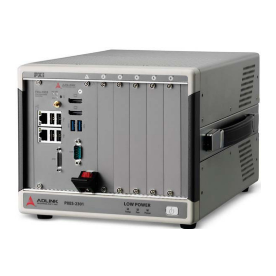
PXES- 2301 for portable use with minimized space requirements. An industrial grade AC power supply delivers 320W performance under 50°C, with superior cooling capability. All in all, the PXES-2301 is an ideal PXI Express platform choice for practically any testing and measurement operation. 1.1 Features ... -
Page 12: Specifications
Leading EDGE COMPUTING 1.2 Specifications The PXES-2301 complies with the PXI-5 Specification Rev.1.0 and accepts all modules compliant with the PXI-5, CompactPCI, and PICMG 2.0 specifications. Power Supply AC Input Rated Input 100-240 VAC, 50-60Hz, 320W max. Entrée d'alimentation CA 100-240 VAC, 50-60Hz, 320W max. - Page 13 PXES-2301 10 MHz System Instrument Clock (PXI_CLK10) Maximum slot-to-slot skew 1 ns Built-in 10 MHz clock Accuracy ±25 ppm 100 MHz System Instrument Clock: PXI_CLK100 Maximum slot-to-slot skew 100 ps Accuracy ±25 ppm Cooling Fans 2 sets of 100.2CFM fans 38.2 W (verified by 50°C...
- Page 14 Leading EDGE COMPUTING Environmental Ambient temperature: -20 to 70°C Storage Relative humidity: 10 to 90%, non-condensing Ambient temperature: 0 to 50°C Operating Relative humidity 10 to 80%, non-condensing Functional shock 30 G, half-sine, 11 ms pulse duration Operating: 5 to 500 Hz, 0.21 Grms, 3 axes Random Vibration Nonoperating: 5 to 500 Hz, 2.46 Grms, 3 axes Sound Pressure Level...
-
Page 15: Schematics
PXES-2301 1.3 Schematics All dimensions are shown in mm (millimeters) NOTE: NOTE: 10.5 177.8 Figure 1-1: Front View Introduction... -
Page 16: Figure 1-2: Left Side View
Leading EDGE COMPUTING 319.6 Figure 1-2: Left Side View 177.8 192.8 Figure 1-3: Right Side View Introduction... -
Page 17: Figure 1-4: Rear View
PXES-2301 Figure 1-4: Rear View Introduction... -
Page 18: Figure 1-5: Top View
Leading EDGE COMPUTING Figure 1-5: Top View Introduction... -
Page 19: Figure 1-6: Underside View
PXES-2301 Figure 1-6: Underside View Introduction... -
Page 20: Connectors, I/O, And Controls
Leading EDGE COMPUTING 1.4 Connectors, I/O, and Controls 1.4.1 Front & Rear Panels Figure 1-7: PXES-2301 Front Panel Introduction... -
Page 21: Figure 1-8: Pxes-2301 Rear Panel
PXES-2301 Figure 1-8: PXES-2301 Rear Panel Feature Details Power Powers the chassis on and off Temperature, Fan, and Power (L Chassis Status LED to R), functions (See “Front Panel LED Indicators” on page 12) In HIGH position, fans operate at... -
Page 22: Backplane
Table 1-3: Front Panel LED Indicators 1.4.2 Backplane PCIe Gen2 x4 PCIe Gen2 x4 PCIe Switch PEX8718 PCIe Gen2 x4 PCIe Gen2 x4 PCIe Gen2 x4 PCIe x1 PCIe Gen2 x4 PCIe/PCI 32bit 33MHz PCI bus (5 VI/O) Bridge Figure 1-9: PXES-2301 PCIE Topology Introduction... -
Page 23: Figure 1-10: Pxes-2301 Backplane
NOTE: NOTE: PCI Express Link Capability The PXES-2301 backplane follows a 4 link x 4 lane PCIe switch fabric configuration, as defined by Compact PCI Express and PXI Express specifications. The backplane routes three system slot x4 PCI Express links to 2nd to 4th peripheral slots directly. - Page 24 Trigger Bus All six PXES-2301 slots share eight trigger lines, through which PXI and PXI Express modules can exchange trigger or clock signals via the trigger bus, allowing precisely timed response to asynchronous external events the system is monitoring or con- trolling.
-
Page 25: Figure 1-11: Trigger Bus Bridge Capability
PXES-2301 Figure 1-11: Trigger Bus Bridge Capability Reference Clock The PXES-2301 backplane supplies a single-ended 10MHz reference clock (PXI_CLK10) and differential 100MHz clock (PXIe_CLK100) to each peripheral slot for inter-module syn- chronization. The independent buffers drive the clock signal to each peripheral slot. - Page 26 Leading EDGE COMPUTING This page intentionally left blank. Introduction...
-
Page 27: Getting Started
PXES-2301 Getting Started This chapter describes procedures for installing the PXES-2301 and making preparations for its operation. Please contact ADLINK or authorized dealer if there are any problems during the installa- tion. Diagrams and illustrated equipment are for reference only. -
Page 28: Cooling Considerations
Leading EDGE COMPUTING 2.2 Cooling Considerations Two 100.2CFM fans on the underside of the PXES-2301 draw cool air through apertures on the bottom and over the PXI/PXIe modules, to be exhausted through the top of the chassis. Getting Started... - Page 29 The PXES-2301 should be situated on a bench top or in an instru- ment rack, maintaining at least 1U (44.5 mm/1.75 in.) clearance from all ventilation apertures. Further, the 12.7mm/0.5 in. height of the rubber feet on the underside must be maintained to allow air intake.
- Page 30 Leading EDGE COMPUTING While the PXES-2301 supports bidirectional setup, chassis direc- tion cannot be configured with the right side carrying handle on the bottom, which can impede cooling functions. To sustain required air flow, always install provided filler panels in unused slots.
-
Page 31: Figure 2-1: Cooling Clearances
PXES-2301 44.45 44.45 44.45 10.5 44.45 Figure 2-1: Cooling Clearances Getting Started... -
Page 32: Hardware Installation
2.3 Hardware Installation 2.3.1 Installing the System Controller The PXES-2301 incorporates a system controller slot supporting a PXI Express system controller of up to 4 slot width. 1. Ensure the CPU, memory module(s), and storage device(s) are properly installed on the system controller 2. - Page 33 PXES-2301 3. Depress the system controller module’s latch to release. Getting Started...
- Page 34 Leading EDGE COMPUTING 4. Align the module’s top and bottom edges with the card guides, and carefully slide the module into the chassis. 5. Lift the latch until the module is securely seated in the chassis backplane Getting Started...
- Page 35 PXES-2301 6. Fasten the screws on the module front panel, and con- nect all devices to the system controller. Getting Started...
-
Page 36: Installing Peripheral Modules
Leading EDGE COMPUTING 2.3.2 Installing Peripheral Modules The PXE-2301 supports up to five peripheral modules, including a system timing module. 1. Select an available peripheral slot (2 to 6) 2. Depress the peripheral module’s latch and align the module’s top and bottom edges with the card guides. 3. - Page 37 PXES-2301 4. Lift the latch until the module is securely seated in the chassis backplane. Getting Started...
-
Page 38: Rack Mounting
To improve efficiency of heat dissipation, after installing desired peripheral modules, please install filler plates for any unused slots. NOTE: NOTE: 2.4 Rack Mounting ADLINK provides hardware for optional installation of the PXES- 2301 to a rack. The kit (order name PXES-2301 Rack Mount Kit) Getting Started... -
Page 39: Single Rack Mount
PXES-2301 flexibly recesses the PXES-2301 in the rack, accommodating external mechanical parts on the front side, such as cables and mass interconnect modules. 2.4.1 Single Rack Mount Figure 2-2: Single Rack Mount Assembly Getting Started... -
Page 40: Figure 2-3: Right Side Bracket Mounting Holes
Leading EDGE COMPUTING For the right side bracket, place screws in the holes marked R. Figure 2-3: Right Side Bracket Mounting Holes And for the left side bracket, use the holes marked L. Figure 2-4: Left Side Bracket Mounting Holes 1.Remove carrying handle from the right side 2.Remove the four rubber feet from the left side Getting Started... -
Page 41: Powering On The System
2.4.2 Powering On the System The PXES-2301 is equipped with a 100 VAC to 240 VAC universal power supply unit requiring no input voltage selection. 1. Connect one end of the supplied power cord to the power inlet located at the rear side of the chassis. - Page 42 Leading EDGE COMPUTING This page intentionally left blank. Getting Started...
-
Page 43: Chassis Monitoring
PXES-2301 Chassis Monitoring The PXES-2301 chassis provides advanced system monitoring and control. Chassis conditions, including internal temperature, fan speed, and DC voltage can all be monitored on the system controller. Communication with the chassis monitoring control unit is avail- able using an embedded controller, such as ADLINK PXIe-3985/ 3975/3935, to access the SMBus located on the system slot (1st slot). -
Page 44: Monitoring The Pxes-2301
Leading EDGE COMPUTING 3.2 Monitoring the PXES-2301 As shown, the ADLINK ChassisWatch for PXES-2301 remote monitoring utility is divided into Connect Control, Remote Status & Control, and Chassis Status categories. Figure 3-1: ADLINK ChassisWatch for PXES-2301 3.2.1 Connect Control Selecting Connect reserves system SMBus. -
Page 45: Figure 3-2: Log Options Dialog
Selecting Load Threshold Settings loads all settings from the saved file. Selecting Load Default Threshold resets all threshold settings to the default values. For details, please see “ADLINK Chas- sisWatch for PXES-2301” on page 34 Version Info Displays the current firmware and board versions. Chassis Monitoring... -
Page 46: Chassis Control And Alarm Threshold Setting
Leading EDGE COMPUTING 3.2.2 Chassis Control and Alarm Threshold Setting Provides operational and threshold settings for the PXES-2301, including trigger bus, PXIe link, target temperature, and fan mode, and threshold settings for DC voltage, temperature, and cooling fan speed. Target Temperature When the Fan switch on the rear panel is set to AUTO, fans run at different speeds based on the measured temperature. -
Page 47: Table 3-1: Target Temperature Parameters Legend
Set. Fan Speed Displays Auto/Full fan speed setting status of the PXES-2301. Auto is displayed when fans are set to auto mode and Full when the fans are set to run at full speed. -
Page 48: Chassis Status
Leading EDGE COMPUTING 3.2.3 Chassis Status DC Voltage Displays monitored 5V Standby, 3.3V, 5V, 12V, and -12V power rail readings. The status displays as normal when the readings are within the threshold range, and abnormal when the thresh- old range is exceeded. Chassis Temperature Temperature sensors T1 to T3, located inside the chassis as shown, provide status, display as normal when under the... -
Page 49: Figure 3-4: Chassis Temperature Sensors
PXES-2301 Figure 3-4: Chassis Temperature Sensors Fan Speed Displays monitored readings of the two cooling fans. Status displays as normal when readings exceed threshold value, and abnormal when the readings fall below the threshold value. Chassis Monitoring... - Page 50 Leading EDGE COMPUTING This page intentionally left blank. Chassis Monitoring...
-
Page 51: A Appendix: Troubleshooting And Maintenance
Appendix A - Troubleshooting and Maintenance This Appendix describes basic troubleshooting techniques, as well as instructions for the maintenance of the PXES-2301 chassis. A.1 Installation Problems Inability to start the system frequently results from incorrect instal- lation of the system controller, peripheral modules, and other com- ponents. -
Page 52: Basic Troubleshooting
The PXES-2301 weights 5.85 kg (12.9 lb). Caution should be exercised when moving the chassis to avoid any possible injury. Troubleshooting and Maintenance... -
Page 53: Cleaning The Exterior
Make sure that the power cord is in good condition before plugging it into the system. It is important to check the reliability of the power source. The PXES-2301 power supply is capable of han- dling 100 to 240 V AC within the 50 Hz to 60 Hz range. Do not connect the PXES-2301 to an already overloaded circuit. - Page 54 This page intentionally left blank. Troubleshooting and Maintenance...
-
Page 55: Important Safety Instructions
PXES-2301 Important Safety Instructions For user safety, please read and follow all instructions, Warnings, Cautions, and Notes marked in this manual and on the associated device before handling/operating the device, to avoid injury or damage. Read these safety instructions carefully. - Page 56 Leading EDGE COMPUTING Secure the power cord (do not place any object on/over the power cord). Only install/attach and operate device on stable surfaces and/or recommended mountings. If the device will not be used for long periods of time, turn off and unplug it from its power source ...
- Page 57 PXES-2301 BURN HAZARD Touching this surface could result in bodily injury. To reduce risk, allow the surface to cool before touching. Important Safety Instructions...
-
Page 58: Consignes De Sécurité Importante
Leading EDGE COMPUTING Consignes de Sécurité Importante S'il vous plaît prêter attention stricte à tous les avertissements et mises en garde figurant sur l'appareil , pour éviter des blessures ou des dommages. Lisez attentivement ces consignes de sécurité. Conservez le manuel de l'utilisateur pour référence future. - Page 59 PXES-2301 Gardez l'appareil éloigné de la chaleur ou de l'humidité élevée. Gardez l'appareil correctement ventilé (ne bloquez pas et ne couvrez pas les ouvertures de ventilation). Utilisez toujours les paramètres de tension et de source d'alimentation recommandés.
- Page 60 Leading EDGE COMPUTING Il est recommandé d'installer l'appareil uniquement dans une salle de serveurs ou une salle informatique où l'accès est: Réservé au personnel de maintenance qualifié ou aux utilisateurs familiers avec les restrictions appliquées à l'emplacement, les raisons de celles-ci et les précautions nécessaires.
-
Page 61: Getting Service
San Jose, CA 95138, USA Tel: +1-408-360-0200 Toll Free: +1-800-966-5200 (USA only) Fax: +1-408-360-0222 Email: info@adlinktech.com ADLINK Technology (China) Co., Ltd. 300 Fang Chun Rd., Zhangjiang Hi-Tech Park Pudong New Area, Shanghai, 201203 China Tel: +86-21-5132-8988 Fax: +86-21-5132-3588 Email: market@adlinktech.com ADLINK Technology GmbH Hans-Thoma-Straße 11...
Need help?
Do you have a question about the PXES-2301 and is the answer not in the manual?
Questions and answers