Advertisement
Quick Links
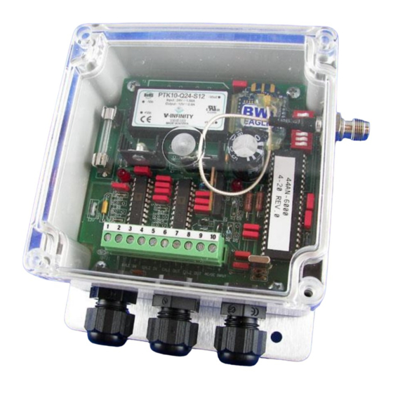
AIR-EAGLE
900 MHz RF Receiver
MODEL 441AN-5000-4-20O-120VAC
DESCRIPTION
The A
-E
XLT,
441AN-5000-4-20120VAC
IR
AGLE
MODEL
receiver capable of receiving two 4-20mA or 0-5VDC input signals from
a remote transmitter(s). Two 4-20mA outputs are provided to relay the
information received. This unit can receive signals from up to 2500 feet
away and is user-programmable for up to eight network frequencies to
allow multiple systems to operate simultaneously in the same area
without interference.
INSTALLATION
Mount the A
-E
XLT RECEIVER in a convenient location
IR
AGLE
1.
2.
Install wiring to output terminal strip.
3.
Install antenna to TNC connector on side of unit.
4.
Plug supplied AC wall plug adapter into 110VAC outlet.
OPTIONS & FREQUENCY SET-UP
This receiver is factory set to operate on frequency #1. If you wish to
change the default setting, follow the instructions using the table below:
1) Remove power from unit and remote top cover/
2) Select desired options and frequency using table below.
3) Reattach cover and apply power. Programming is now complete.
SEL1
OPEN
SWITCH
NUMBER
Uses Safety Timer
SW1
Select whether output holds or clears when signal lost
4mA Idle
(default)
SW2
Select whether safety timer clears the output low or high
SW3 &4
Reserved for future use
FREQUENCY SET-UP
Network
Frequency
1
(default)
2
3
SEL1
(SW5-7)
4
5
6
7
8
105 Bonnie Drive
Butler, PA 16002
724-283-4681
724-283-5939 (fax)
www.bwieagle.com
®
XLT
s an RF
I
OPTIONS
CLOSED
(default)
No Safety Timer
20mA Idle
SW5
SW6
OPEN
OPEN
OPEN
CLOSED
OPEN
OPEN
OPEN
CLOSED
OPEN
CLOSED
CLOSED
OPEN
OPEN
OPEN
CLOSED
CLOSED
OPEN
CLOSED
OPEN
CLOSED
CLOSED
CLOSED
CLOSED
CLOSED
PRODUCT INFORMATION
Dimensions (with mounting plate) 6.3" L x 4.8" W x 2.3" H
TERMINAL STRIP WIRING
1
2
CONTROLS & INDICATORS
SW7
OUTPUT
FAULT LEDS
BULLETIN
3
4
5
6
7
Each Channel has a
RED
when the current output is open
8
9
10
LED that will turn on
Advertisement

Related Manuals for BWI Eagle AIR-EAGLE XLT 441AN-5000-4-20O-120VAC


Summary of Contents for BWI Eagle AIR-EAGLE XLT 441AN-5000-4-20O-120VAC
- Page 1 105 Bonnie Drive PRODUCT INFORMATION Butler, PA 16002 724-283-4681 BULLETIN 724-283-5939 (fax) www.bwieagle.com ® AIR-EAGLE 900 MHz RF Receiver MODEL 441AN-5000-4-20O-120VAC DESCRIPTION The A XLT, 441AN-5000-4-20120VAC s an RF AGLE MODEL receiver capable of receiving two 4-20mA or 0-5VDC input signals from a remote transmitter(s).
- Page 2 Some jurisdictions do not allow the exclusion of implied warranties so this limitation may not apply to you. To obtain warranty service, contact BWI Eagle for a return Inputs Not used on this model material authorization.
- Page 3 441AN-5000-4-20-120VAC 4-20mA Installation The above diagram shows the channel 1 output hooked to a 4-20mA receiver or PLC. The input resistance of the receiver can be up to 500 ohms. Anything higher and the current will be limited to below 20 mA since the maximum output voltage of the channel outputs is 10 volts.