Advertisement
Quick Links
Advertisement

Related Manuals for BluDot Modu-licious Bedside Table


Summary of Contents for BluDot Modu-licious Bedside Table
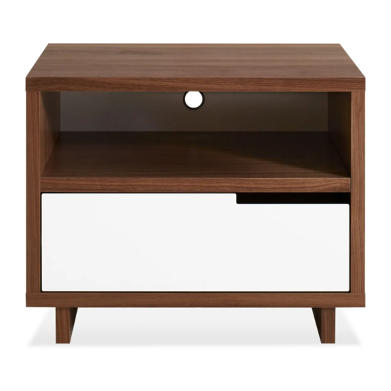
- Page 1 K E E P T H E S T U F F Y O U L I K E A N D S T O R E I T W E L L . N E E D A H A N D ? Contact us at service@bludot.com or Drawers and doors are your canvas with the award-winning 844.425.8368 for assistance.
-
Page 2: Parts & Hardware
Parts & Hardware Foot Drawer Slide Stretcher Shelf Panel Side Panel Drawer Bottom Panel Top Panel Back Panel 1 | 8 4 4 . 4 2 5 . 8 3 6 8 M O D U - L I C I O U S B E D S I D E T A B L E... - Page 3 Parts & Hardware Pt. 5001 Pt. 1023 Pt. 4005 Pt. 8018 Pt. 5002 Pt. 5005 A S S E M B L Y N O T E S S E R V I C E @ B L U D O T . C O M | 2...
-
Page 4: How To Use The Cam Lock System
How to use the cam lock system Note direction of cam arrow. Turn cam clockwise 1/2 turn or until tight. Note direction of cam arrow. 3 | 8 4 4 . 4 2 5 . 8 3 6 8 M O D U - L I C I O U S B E D S I D E T A B L E... - Page 5 Step 01 A S S E M B L E B A S E . Using the stretcher and feet assemble the base as shown. Refer to Page 3 on how to use the cam lock system. Finished Edge PT. 50 0 1 x 2 PT.
- Page 6 Step 02 AT TA C H B O T T O M PA N E L . Attach the bottom panel to the base using the provided hardware as shown. Refer to page 3 on how to use the cam lock system. Bottom Panel PT.
- Page 7 Step 03 AT TA C H D R A W E R S L I D E S . Attach drawer slides to side panel as shown using the provided hardware. Repeat for left side panel. Right Side Panel PT. 1 02 3 X 4 A S S E M B L Y N O T E S S E R V I C E @ B L U D O T .
- Page 8 Step 04 B E G I N A S S E M B L I N G C A S E . Attach side panels to shelf panel as shown using the provided hardware. Be sure to align grooves on side panels. Refer to page 3 on how to use the cam lock system.
- Page 9 Step 05 AT TA C H B A S E . Attach the base as shown using the provided hardware. Refer to page 3 on how to use the cam lock system. PT. 5 00 1 x 6 PT. 5 0 02 x 6 PT.
- Page 10 Step 06 I N S E R T T H E B A C K PA N E L . Add rubber grommet to back panel as shown. Insert back panel into grooves in case. PT. 80 18 X 1 9 | 8 4 4 .
- Page 11 Step 07 F I N I S H A S S E M B L I N G C A S E . Finish assembling the case by attaching the top panel as shown using the provided hardware. Refer to page 3 on how to use the cam lock system.
-
Page 12: Additional Information
Additional Information TO REMOVE DRAWERS Pull lever up on the right side and push down on the left side of the drawer slide. With levers engaged pull drawer out. TO ADJUST DRAWER FRON TS Loosen the acorn nuts, adjust drawer front, re-tighten acorn nuts.
Need help?
Do you have a question about the Modu-licious Bedside Table and is the answer not in the manual?
Questions and answers