
Related Manuals for Zanussi ZGG65411


Summary of Contents for Zanussi ZGG65411
- Page 1 User Manual GETTING STARTED? EASY. ZGG65411 ZGG65414 ZGG65XS414 EN User Manual...
-
Page 2: Safety Information
SAFETY INFORMATION Before the installation and use of the appliance, carefully read the supplied instructions. The manufacturer is not responsible for any injuries or damages that are the result of incorrect installation or usage. Always keep the instructions in a safe and accessible location for future reference. -
Page 3: Safety Instructions
CAUTION: The cooking process has to be supervised. A short • term cooking process has to be supervised continuously. WARNING: Danger of fire: Do not store items on the cooking • surfaces. Metallic objects such as knives, forks, spoons and lids should •... -
Page 4: Electrical Connection
appliance and the upper drawer, is sufficient for • Use only correct isolation devices: line air circulation. protecting cut-outs, fuses (screw type fuses • The underside of the appliance can get hot removed from the holder), earth leakage trips when in use. If an oven has not been fitted and contactors. - Page 5 • The vapours that very hot oil releases can cause • Discoloration of the enamel or stainless steel spontaneous combustion. has no effect on the performance of the • Used oil, that can contain food remnants, can appliance. cause fire at a lower temperature than oil used CARE AND CLEANING for the first time.
-
Page 6: Product Description
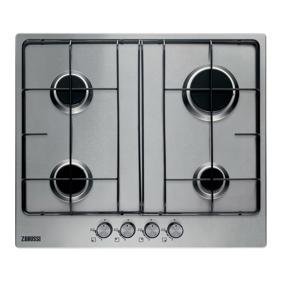
PRODUCT DESCRIPTION COOKING SURFACE LAYOUT Semi-rapid burner Rapid burner Auxiliary burner Control knobs CONTROL KNOB Symbol Description Symbol Description minimum gas supply no gas supply / off position ignition position / maximum gas supply DAILY USE WARNING! Refer to Safety chapters. -
Page 7: Burner Overview
BURNER OVERVIEW 3. Adjust the flame after it is regular. If after some tries the burner does not light, check if the crown and its cap are in correct positions. WARNING! Do not keep the control knob pushed for more than 15 seconds. -
Page 8: Care And Cleaning
DIAMETERS OF COOKWARE WARNING! Do not put unstable or damaged pots on the burner to Use cookware with diameters prevent from spill and injury. applicable to the size of burners. CAUTION! Make sure that the bottoms of pots do not stand above Diameter of cook- Burner the control knob, otherwise the flame... -
Page 9: Periodic Maintenance
can cause damage to the hob. Take care to avoid burns. • Remove when the hob is sufficiently cool: limescale rings, water rings, fat stains, shiny metallic discoloration. Clean the hob with a moist cloth and non-abrasive detergent. After cleaning, wipe the hob dry with a soft cloth. •... -
Page 10: Installation
IF YOU CANNOT FIND A SOLUTION... The instructions about the Service Centre and conditions of guarantee are in the guarantee If you cannot find a solution to the problem yourself, booklet. contact your dealer or an Authorised Service Centre. Give the data from the rating plate. Make LABELS SUPPLIED WITH THE ACCESSORIES sure, you operated the hob correctly. -
Page 11: Injectors Replacement
A. End of shaft with nut installed in a room of volume between 5 m³ and 10 B. Washer supplied with the appliance m³ an air vent of effective area of 50 cm² is C. Elbow supplied with the appliance required, while if the volume exceeds 11 m³... - Page 12 2. Turn the knob on the minimum position. The hob has a terminal block which is 3. Remove the knob. marked as follows: 4. With a thin screwdriver, adjust the bypass • L — Live terminal screw position (A). • N —...
- Page 13 REPLACEMENT OF THE CONNECTION ASSEMBLY CABLE The replacement of electric cable must be carried out exclusively by the service force centre or by personnel with similar competencies, in accordance with the current regulations. To replace the connection cable use only H03V2V2-F T90 or equivalent type.
-
Page 14: Possibilities For Insertion
A) supplied seal If a furniture unit is installed at a B) supplied brackets distance of 400 mm above the hob, there must be a minimum safety distance of 50 mm to the left or right from the edge of the hob. -
Page 15: Technical Data
Kitchen unit with oven The electrical connection of the hob and the oven must be installed separately for safety reasons and to let easy remove oven from the unit. TECHNICAL DATA HOB DIMENSIONS Width 594 mm Depth 510 mm BYPASS DIAMETERS BURNER Ø... -
Page 16: Energy Efficiency
GAS BURNERS FOR LPG G30/G31 28-30/37 MBAR NOMINAL GAS FLOW g/h NORMAL MINIMUM INJECTOR BURNER POWER kW POWER kW MARK G30 28-30 mbar G31 37 mbar Rapid 0,75 Semi-rapid 0,45 Auxiliary 0,33 ENERGY EFFICIENCY PRODUCT INFORMATION ACCORDING TO EU 66/2014 Model identification ZGG65411XB;... - Page 20 WWW.ZANUSSI.COM/SHOP...
Need help?
Do you have a question about the ZGG65411 and is the answer not in the manual?
Questions and answers