Table of Contents
Advertisement
Quick Links
Advertisement
Table of Contents

Related Manuals for Zanussi ZGG 643


Summary of Contents for Zanussi ZGG 643
- Page 1 à à INSTRUCTION BOOKLET...
-
Page 3: For Your Safety
Repairs carried out by installing a cooker hood with discharge tube. unexperienced persons may cause injury or serious malfunctioning. Refer to your local Zanussi Service • In case of intensive or long time use of the Centre. Always insist on genuine Zanussi spare appliance, make the ventilation more efficient, parts. -
Page 4: Table Of Contents
Contents 1. Instruction for the User ..... Pag. 5. Electrical Connection ....Pag. 6. Adaptation to different 2. Cleaning and Maintenance ..Pag. types of gas........ Pag. 3. Technical Data ......Pag. 7. Building In ........Pag. 4. Instruction for the Installer ..Pag. Guarantee ........ -
Page 5: Cleaning And Maintenance
2. Cleaning and Maintenance • Disconnect the appliance from the electrical supply, before carrying out any cleaning or manteinance work. Wash the enamelled components with warm soapy water. Never use abrasive cleaners Frequently wash the "caps" and the "crowns" with hot soapy water, carefully taking away any built-up of food. -
Page 6: Technical Data
3. Technical Data Gas Burners Rating Gas connection G 1/2" Rapid Burner (big) 2,9 kW (G20/G25) - 2,7 kW (G30/G31) Electric Supply 230 V 50 Hz Auxiliary Burner (small) 1 kW Semirapid Burner (medium) 2 kW HOB RECESS DIMENSIONS Category II 2E+3+ Length 550 mm. -
Page 7: Electrical Connection
5. Electrical Connection The appliance is designed to be connected to 230 V monophase electricity supply. The connection must be carried out in compliance with the laws and regulations in force. Before the appliance is connected: 1) check that the main fuse and the domestic installation can support the load (see the rating label);... -
Page 8: Adaptation To Different Types Of Gas
6. Adaptation to different types of gas INJECTORS REPLACEMENT • Remove the pan supports. • Remove the burner's caps and crowns. • With a socket spanner 7 unscrew and remove the injectors (Fig. 6), and replace them with the ones required for the type of gas in use (see table 2). -
Page 9: Building In
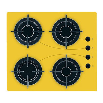
7. Building In A = Auxiliary burner SR = Semirapid burner R = Rapid Burner These hobs can be inserted in a built-in kitchen unit whose depth is between 550 and 600 mm. The hobs dimensions are shown in Fig. 9. The edge of the cut out must have a minimum distance from the rear wall of 55 mm. - Page 10 POSSIBILITIES FOR Kitchen unit with oven INSERTION The hob recess dimensions must comply the indication given in Figs. 12 and 13 and must be provided with Kitchen unit with door brackets to allow a continuous supply of air. Proper arrangements must be taken in designing the To avoid overhating, the building in should be carried forniture unit, in order to avoid any contact with the out as shown in Figs.
-
Page 11: Guarantee
DECLARATION OF GUARANTEE TERMS (BELGIUM) Our appliances are produced with the greatest of non-original accessories or spare parts are not care. However, a defect may still occur. Our consumer covered by the guarantee. services department will repair this upon request, 10.
Need help?
Do you have a question about the ZGG 643 and is the answer not in the manual?
Questions and answers