Advertisement
Quick Links
1. Safety Notices
The instrument meets IEC 1010 clauses (the safety standards promulgated by International Electrotech-
nical Commission) in terms of design, and shall be used after reading the safety notices.
• Do not input values over the maximum range of each measurement to avoid damages of the Meter.
• The voltage of below 36V is safe. When the voltage measured is higher than DC36V or AC25V, users
shall check when the multimeter probe is reliably contacted, correctly connected, and well insulated, in
order to avoid electric shock;
• Be sure to keep the test leads off the testing points when switching function or range.
• Select correct function and range to avoid fault operation.
• Please do not measuring before battery isn't installed and back cap isn't firm.
• Do not input any voltage when measure resistance.
• Always remove the test leads before replacing the battery or fuses.
• Do not input a current higher than 20A when measuring the current.
• The following safety symbols may appear in this manual or on the instrument:
•
Attention! Exists high voltage,
2. Specification
2.1. General feature
• Display mode: Liquid crystal display;
• Max display: 1999 (3 ½) digits automatic polarity display.
• Measuring method: Dual-integral A/D conversion;
• Sampling rate: Around 3 times/ second;
• Ultra-range display: Highest position displayed as "OL";
• Low voltage display: Appearance of the sign
• Working environment: (0~40)°C, relative humidity <80%;
• Power supply: 9V battery
• Volume (dimensions): 190 x 88,5 x 27,5mm (L×W×H)
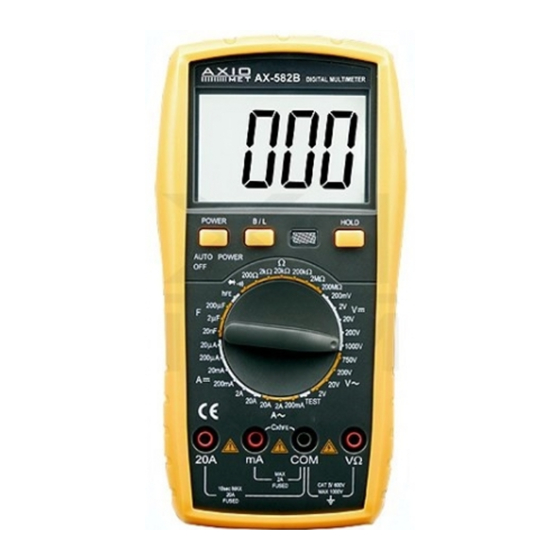
Axiomet AX-582B
GND,
Dual insulation,
;
Must refer to manual,
Low battery
Advertisement

Related Manuals for Axio MET AX-582B


Summary of Contents for Axio MET AX-582B
- Page 1 Axiomet AX-582B 1. Safety Notices The instrument meets IEC 1010 clauses (the safety standards promulgated by International Electrotech- nical Commission) in terms of design, and shall be used after reading the safety notices. • Do not input values over the maximum range of each measurement to avoid damages of the Meter.
- Page 2 • Weight: Around 320g (including battery); • Accessories: 20A test leads, user manual, holster, gift box, and 9V battery. 2.2. Technical characteristics 2.2.1. Accuracy ± (a% of the reading + least significant bit); guaranteed accurate ambient temperature: (23±5)° C; relative humidity: <75%;...
- Page 3 2A / ±(1.5%+10) / 1mA 20A / ±(2.0%+5) / 10mA Maximum voltage drop measured: Full range mA: 200mV Maximum input current: 10A (not more than 10s); Overload protection: 0.2A/250V fuse; 20A/250V fuse. 2.2.5. AC current measurement Range / Accuracy / Resolution 200mA / ±(1,5%+15) / 100uA 2A / ±(2.0%+5) / 1mA 20A / ±(3.0%+10) / 10mA...
- Page 4 2.2.8. Square Wave Output Range: Voltage: about 3,3V Frequency: 50 Hz~5KHz Input protection: 500Vrms 2.2.9. Diodes and Continuity Measurement Value displayed: Forward voltage drop of diode Testing condition: Forwrd DCA is approx. 1mA, the backward voltage is approx. 3V Value displayed:Buzzer sounds, the resistance is less than (50 ± 20) Ω Testing condition: Open voltage is approx.
-
Page 5: Application Method
3. Application Method 3.1. Description of operating panel • 1. LCD unit: It displays the numerical value measured with the instrument and its unit; • 2-1. Power ON/OFF • 2-2. HOLD, B/L • 2-3. MIN/MAX key... - Page 6 • 2-4. Buzzer indicator lamp • 3. Knob switch: Used to change the measuring function and range; • 4. Voltage, resistance and frequency COM • 5. GND, the anode COM of test accessory. • 6. 0,2A current test COM, the cathode COM of test accessory •...
- Page 7 • If having no idea about the scope of current measured, users shall rotate the range switch to the highest level, and then rotate it to corresponding level according to the value displayed; • If LCD shows “OL”, it indicates going beyond the range, and the range switch shall be rotated to a higher level.
- Page 8 3.7. Capacitance measurement • Insert the black multimeter probe into “COM” end, and the red multimeter probe into “VΩHz” end; • Select the knob to proper capacitance range, Notes • If the capacitance under tested is over the max. Value of selected range, LCD displays “OL”, thus should select the knob to a higher range.
-
Page 9: Maintenance Of The Instrument
3.11. Data holding, B/L Press the “Hold B/L” switch, the presently measured value is held on LCD, press it again, the function is cancelled. Press “Hold B/L” key to turn on the backlight 3.12. Automatic power off • The meter will be into sleeping mode when it works for (15±10) minutes. Press “POWER” key twice to restart the power. -
Page 10: Troubleshooting
5. Troubleshooting If your instrument does not work normally, the following methods may help you solve common problems. If the troubles can not still be eliminated, please contact our maintenance center or dealer. Fault phenomena - Position to be inspected and method No display - The power supply is not connected;...
Need help?
Do you have a question about the AX-582B and is the answer not in the manual?
Questions and answers