Advertisement
Quick Links
AX-160IP - TOUCH PAD DIGITAL MULTIMETER - USER'S
MANUAL
1. GENERAL INSTRUCTIONS
1.0.
This instrument complies with IEC 61010-1, CAT III 1000V and CAT IV 600V overvoltage standards. See
Specifications.
- Touch pad operation.
- 6000counts, daul value display.
- IP65 water jets.
- CAT III 1000V / CAT IV 600V application.
- Auto backlight.
- Digital calibration.
- 2 colour backlight for various operate status indication.
- Chargeable battery selection/ MicroUSB charge
To get the best service from this instrument, please read carefully this user's manual and respect the
detailed safety precautions.
International symbols used on the meter and in this manual are explained in chapter 1.2.
1.1. Precautions safety measures
1.1.1. Preliminary
* As the possibilities of high transient overvoltages occurred in today's power systems increase, more
stringent safety standards are set for the electrical test equipment. Transients on electrical systems(power
grid, feeder or branch circuits) will trigger a series of incidents that may result in serious personal injury.
To protect you against transients, safety must be built into the test equipment.
Overvoltage category /// In brief /// Examples
- CATI/// Electronic /// • Protected electronic equipment.
• Equipment connected to (source) circuits in which measures are taken to limit transient overvoltages to
an appropriately low level.
• Any high-voltage, low-energy source derived from a highwinding resistance transformer, such as the
high-voltage section of a copier.
- CATII/// Single-phase receptacle connected loads /// • Appliance, portable tools, and other household and
similar loads.
Advertisement

Related Manuals for Axio MET AX-160IP


Summary of Contents for Axio MET AX-160IP
- Page 1 AX-160IP - TOUCH PAD DIGITAL MULTIMETER - USER’S MANUAL 1. GENERAL INSTRUCTIONS 1.0. This instrument complies with IEC 61010-1, CAT III 1000V and CAT IV 600V overvoltage standards. See Specifications. - Touch pad operation. - 6000counts, daul value display. - IP65 water jets.
- Page 2 • Outlet and long branch circuits. • Outlets at more than 10 meters (30 feet) from CAT III source. • Outlets at more that 20 meters (60 feet) from CAT IV source. - CAT III /// Three-phase distribution, including single-phase commercial lighting /// • Equipment in fixed installations, such as switchgear and polyphase motors.
- Page 3 disconnecting, disconnect the live test lead before disconnecting the common test lead. * Before changing functions, disconnect the test leads from the circuit under test. * For all DC functions, including manual or auto-ranging, to avoid the risk of shock due to possible improper reading, verify the presence of any AC voltages by first using the AC function.
- Page 4 you are not charged with static electricity, which may destroy internal components. * Any adjustment, maintenance or repair work carried out on the meter while it is live should be carried out only by appropriately qualified personnel, after having taken into account the instructions in this present manual.
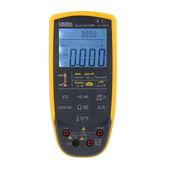
- Page 5 2. DESCRIPTION 2.1. Instrument Familiarization The front panel is shown as in Fig. 2-1, explanation being as follows: 1 LCD display 2 Auxiliary function key pads...
- Page 6 3 Measurement function key pads 4 mA / uA socket (uA, mA range red testlead input) 5 10A socket (A range red testlead input) 6 COM socket (black testlead input) 7 V Terminal (red testlead for voltage, resistance, capacitance, frequency, Temperature, diode and conti- nuity measurements) 8 Light sensor (Use for auto backlight) 2.2.
- Page 7 14 - - The number of the data you saved. 15 - - Platinum thermal resistance. 16 - - Measurement units in the sub-display zone. 17 - - Indicates the meter is locked. 18 - - The meter is in the Autorange mode in which the meter automatically selects the range with the best resolution.
- Page 8 Number -- Explanation 1 -- 1.Slide this key to lock or unlock the digital multimeter. 2.Slide down this key we can turn on the machine. 3.Slide up this key twice quickly, we can turn off the meter. 2 -- When you measure the voltage, resistance or current. 1.Touch RANGE 2 once to enter the manual ranging mode.
-
Page 9: Function Description
3. FUNCTION DESCRIPTION 3.1. General Functions 3.1.1. DATA HOLD mode Data Hold mode makes the meter stop updating the displaying. If you want to exit this mode, you can change the measurement which you need. 1.Touch the key 5 once. Fixes the display on the current value, the symbol H is displayed on the screen. 2. - Page 10 ence between the reference value and subsequent reading is displayed. 3. Touch REL key again to return the Meter to normal operation. 3.1.5. Memory mode For this function,the meter will save the data you need. we can save 10 data at most. To enter and exit the memory mode: 1.Touch SHIFT key ,the symbol will be displayed on the screen.
- Page 11 3.1.11. Automatic Power off When there is no any keys to be pressed, it reached the time you set. The buzzer will ring four times, and then the device will turn off. 1.Turn on the device. And then press the key 6 three times quickly. 2.Touch the key 5 or 7 to select the time you want to set.
- Page 12 3. Touch the key 2, the symbol “MANU” will be displayed on the LCD. 4. Touch the key 5 or 7 to select the range you need. There are three modes, including 0-20mA%, 0-24 mA%, 4-20 mA%. 5 Touch the key 10 again to exit. 3.1.18.
- Page 13 3.1.20. Function table PAD // Default function // Alternate function // Range key selection // Range key reach function // DC V // - // YES // N/A // - // AC V + Hz // YES // N/A // DC mV // - // YES // N/A // - // AC mV + Hz // YES // N/A // - // Frequency + Duty // N/A // N/A // CONT // - // N/A // N/A...
- Page 14 3.2.1.3. DC VOLTAGE 1. Turn on the device. 2. The meter will enter the DCV range. 3. Connect the black and red test leads to the COM and V terminals respectively. 4. Connect the test leads to the circuit being measured 5.
- Page 15 3.2.1.4. mv VOLTAGE 1. Turn on the device. 2. Touch the key 11 once to enter the DCmV range. Touch the key twice to enter the ACmV range. Touch it three times, it will enter the frequency measurement mode. 3. Connect the black and red test leads to the COM and V terminals respectively. 4.
- Page 16 For better accuracy when measuring the DC offset of an AC voltage, measure the AC voltage first. Note the AC voltage range, then manually select a DC voltage range 3.2.2. Resistance measurement To avoid electrical shock and/or damage to the instrument, disconnect circuit power and discharge all high-voltage capacitors before measuring resistance.
- Page 17 3.2.3. Capacitance measurement To avoid electrical shock and/or damage to the instrument, disconnect circuit power and dis- charge all high-voltage capacitors before measuring capacitance. Use the dc voltage function to confirm that the capacitor is discharged. The Meter’s capacitance ranges are 60.00nF, 600.0µF, 6.000 F, 60.00µF and 300.0µF. To measure capacitance (set up the Meter as shown in Figure 3-3): 1.Touch Ω...
- Page 18 2. Connect the black and red test leads to the COM and terminals respectively (or you can use capacitor test lead). 3. Connect the test leads to the capacitor being measured and read the displayed value. Some tips for measuring capacitance: •...
- Page 19 3.2.4. Continuity Check To avoid electrical shock and/or damage to the instrument, disconnect circuit power and discharge all high-voltage capacitors before testing for Continuity. To test for continuity (set up the Meter as shown in Fig. 3-4): 1. Touch the key 9 once to enter the continuity check mode. 2.
- Page 20 To test a diode out of a circuit (set up the Meter as shown in Fig. 3-5): 1. Touch the key 9 twice to enter the Diode Test mode. 2. Connect the black and red test leads to the COM and VΩ terminals respectively. 3.
- Page 21 4. Connect the test leads tip in parallel with the circuit to be measured. And don’t touch any electrical conductors. 5. Touch mvHz key 11 again to exit. NOTE: In noisy environment, it is preferable to use shield cable for measuring small signal 3.2.7.
- Page 22 To measure temperature: 1. Touch the key 14,the temperature will be shown in the subdisplay zone. Sub-display show an- other unit. 2. Insert the ‘K’ type thermocouples into the COM terminal and ℃ terminal. Please make sure the polarity is correct. 3.
- Page 23 3.2.8. Current measurement To avoid damage to the Meter or injury if the fuse blows, never attempt an in-circuit current measurement where the open-circuit potential to earth is greater than 1000V. To avoid damage to the meter, check the meter’s fuse before proceeding. Use the proper termi- nals, function, and range for your measurement.
- Page 24 To measure the uA and mA 1. Turn off the power of the circuit. Discharge all high voltage capacitors. 2. Touch the key 10 once to select the DC uA and DC mA range. Touch it twice to the AC uA and AC mA range.
-
Page 25: Technical Specifications
3.3. PC Link The meter has serial data transmission function. It can be connected with PC by USB interface, so the measured data can be recorded, analyzed, processed and printed by PC. Before using this function, you need to install the PC-Link software and USB driver in your PC. 1.Touch the key 6, the symbol “... - Page 26 4.2. Measurement specifications 4.2.0. Accuracy is specified for one year after calibration, at operating temperatures of 18℃ to 28℃, with relative humidity at less than 80%. Accuracy specifications take the form of: ± (% of Reading + Number of Least Significant Digits) 4.2.1.
- Page 27 99.99kHz /// 0.01kHz /// ±(0.1% of rdg+3digits) 999.9kHz /// 0.1kHz /// ±(0.1% of rdg+3digits) Linear frequency (6HZ~10KHZ) Range /// Resolution /// Accuracy 99.99Hz /// 0.01 Hz /// ±(0.05% of rdg+5digits) 999.9Hz /// 0.1 Hz /// ±(0.05% of rdg+5digits) 9.999kHz /// 0.001kHz /// ±(0.05% of rdg+5digits) Above accuracies can be guaranteed within 10%~100% of the full range.
- Page 28 4.2.7. K-type Thermocouple Temperature Range /// Resolution /// Accuracy -200℃~0℃ /// 0.1℃ /// ±(3.0% of rdg + 3℃) 1℃~400℃ /// 0.1℃ /// ±(2.0% of rdg+ 3℃) 401℃~1000℃ /// 1℃ /// ±2.0% of rdg Note: The specifications of temperature don’t include thermocouple errors. 4.2.8.
-
Page 29: Maintenance
5. MAINTENANCE 5.0. This section provides basic maintenance information, including fuse and battery replacement instructions. Do not attempt to repair or service your Meter unless you are qualified to do so and have the relevant calibration, performance test, and service information. 5.1. - Page 30 1. Disconnect test leads and/or any connectors from the terminals. 2. Use a screwdriver to unlock the screws on the battery cover. 3. Take out the battery cover from the meter. 4. Remove the used battery. 5. Replace with 2pcs new AA battery. 6.
Need help?
Do you have a question about the AX-160IP and is the answer not in the manual?
Questions and answers