Table of Contents
Advertisement
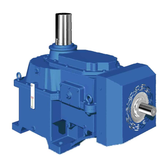
PARAMAX
SFC Series
for Cooling fan
CAUTION
These products should be handled, installed, and maintained by trained technicians.
Carefully read the maintenance manual before use.
Oil is removed from these products before shipment. Supply oil according to the
maintenance manual before operation.
A copy of this maintenance manual should be sent to the actual user.
This maintenance manual should be kept by the user for future reference.
®
Maintenance Manual
No.GM2201E-5
Advertisement
Table of Contents

Related Manuals for Sumitomo Drive Technologies PARAMAX SFC Series


Summary of Contents for Sumitomo Drive Technologies PARAMAX SFC Series
- Page 1 PARAMAX ® SFC Series for Cooling fan CAUTION These products should be handled, installed, and maintained by trained technicians. Carefully read the maintenance manual before use. Oil is removed from these products before shipment. Supply oil according to the maintenance manual before operation. A copy of this maintenance manual should be sent to the actual user.
-
Page 3: Table Of Contents
(Safety and other precautions) Carefully read this maintenance manual and all accompanying documents before use (installation, operation, maintenance, inspection, etc.). Thoroughly understand the machine, information about safety, and all precautions for correct operation. Maintain this manual for future reference. Pay particular attention to the "DANGER" and "CAUTION" warnings regarding safety and proper use. DANGER : Improper handling may result in physical damage, serious personal injury and/or death. -
Page 4: Inspection Upon Delivery
1. Inspection upon delivery CAUTION ● Unpack the unit after verifying that it is positioned right side up ; otherwise, injury may result. ● Verify that the unit received is in fact the one ordered. When a different product is installed, injury or damage to the system may result. ● Do not remove nameplate. Upon delivery of these products, check the following : (1) The descriptions on the rating plate conform to your order. (2) There were no parts damaged during transport. (3) All bolts and nuts are firmly tightened. If there is any doubt that the unit delivered does not conform to the one ordered, contact the nearest agent, distributor or service office. -
Page 5: Storage
2. Storage When storing these products for any extended periods of time before use, consider the following important points. 2-1) Temporary storage (1) Store these products in a clean, dry, covered storage area. • Do not store these products outdoors or in a wet location. 2-2) Long-term storage (1) The oil seal will deteriorate when exposed to high temperatures and UV rays. Inspect and replace the oil seal after long-term storage if there are any signs of damage or cracking. (2) After starting these products, check that it is free from abnormal sound, vibration, or heatbuild-up. (If any kind of anomaly is observed) contact the nearest agent, dealer, or service office immediately. -
Page 6: Coupling With Other Machines
4-1) Location of installation Ambient temperature : 0°C to +40°C (+32°F to +104°F) Ambient humidity : 85% max.(Air vent or air breather must be located outside of fan stack with extended piping) Ambient atmosphere : There shall be no corrosive gas, explosive gas. The installation space shall be well ventilated, and free from dust. Location of installation : Indoors or outdoors. • Special specifications are necessary when installation conditions are other than those mentioned here. -
Page 7: Lubrication
5-1) Installation coupler Shaft • When attaching a coupler, be careful not to apply impact force or excessive Coupler thrust to the shaft ; otherwise, the bearing may be damaged. • Shrink fit or shaft-end thread is recommended for mounting (Fig. 3) The dimensions (A, B, and X) illustrated in Fig. 4 shall be within the tolerance shown in Table 2. Shaft end thread Fig. -
Page 8: Backstop
Table 4 Recommended lubricants ● Mineral Oil EXXON TOTAL Brand ARAL CASTROL CHEVRON TEXACO SHELL GULF MOBIL FINA ELF GEAR MOBIL- EP LUBRI- ISO VG320 DEGOL ENERGOL ALPHA OPTIGEAR TRIBOL MEROPA SHELL OMALA CARTER COMPOUNDS GEAR 600 CANT AGMA 6EP BG320 GR-XP-320 SP320 BM 320 1100/320 WM320 S2 G 320 EP320... -
Page 9: Operation
8. Operation DANGER ● Never approach or touch any rotating parts (shaft, etc.) during operation. Loose clothing caught in these rotating parts may result in severe injury and/or death. CAUTION ● Check the oil level with the oil gauge before operation. ● When using pole change motors to change from high speed to low speed, control the fan rotation speed so that regeneration braking torque does not act on the reducer. ● If the reducer has a backstop installed and the reducer is not operated for an extended period, operate the unit a minimum of 5 minutes for every 200 hours of non-operation. ● The reducer will get very hot during operation. Do not touch or come in contact in any way with the reducer ; otherwise, you may suffer burns. -
Page 10: Daily Inspection And Maintenance
9. Daily inspection and maintenance DANGER ● Never approach or touch any rotating parts (shaft, etc.) when maintaining or inspecting the reducer during operation. Loose clothing cought in these rotating parts may result in severe injury and/or death. ● Be sure to stop both the driving and driven machines before checking any tooth surfaces; otherwise, you may be caught in the gear engaging section, resulting in severe injury and/or death. -
Page 11: Troubleshooting
10. Troubleshooting CAUTION ● Promptly identify and correct, according to instructions in this maintenance manual, any abnormalities observed during operation. Do not operate until abnormality is corrected. When any abnomality occurs in the reducer, refer to the following table and take appropriate measures as soon as possible. If they are not repairable, contact the nearest agent, distributor or service office. Table 8 Details of trouble Cause Correction The input shaft rotates, but the output shaft Damage due to overloaded gears or Confer with authorized service station. will not. shafts The key is out of position Place the key in position... -
Page 12: Construction Drawing
12. Construction drawing 4101 6002 6502 4121 7602 6003 4103 3603 3604 4110 6010 4622 POS.NO Part Name 2501 Slow speed shaft 3601 Helical gear 3602 Helical pinion shaft 3603 Bevel gear 3604 Bevel pinion shaft 4101 4103 4110 4121 4122 4124 4622 Tolerance ring 6001 Tapered roller bearing... -
Page 13: Locations Of Oil Filler And Drain Plug
4101 6002 6502 4121 6003 4103 3603 3604 4110 6010 4622 POS.NO Part Name 2501 Slow speed shaft 3601 Helical gear 3602 Helical pinion shaft 3603 Bevel gear 3604 Bevel pinion shaft 4101 4103 4110 4121 4122 4124 4622 Tolerance ring 6001 Tapered roller bearing 6002 Tapered roller bearing 6003... -
Page 14: Warranty
14. Warranty The scope of our warranty for our products is limited to the range of our manufacture. Warranty (period and contents) The warranty period for the Products shall be 18 months after the commencement of delivery or 18 months after Warranty the shipment of the Products from the seller's works or 12 months from the Products coming into operation, Period... - Page 16 Worldwide Locations Singapore U.S.A France SM-Cyclo France SAS (SMFR) Sumitomo (SHI) Cyclo Drive Asia Paci c Pte. Sumitomo Machinery Corporation of America Ltd. (SCA) (SMA) 8 Avenue Christian Doppler, 77700 Serris, France 4200 Holland Blvd. Chesapeake, VA 23323, U.S.A. 15 Kwong Min Road, Singapore 628718 TEL (33)164171717 FAX (33)164171718 TEL (1)757-485-3355...
Need help?
Do you have a question about the PARAMAX SFC Series and is the answer not in the manual?
Questions and answers