Nastec 4HS Installation And Operating Manual
Hide thumbs
Also See for 4HS:
- Installation and operating manual (13 pages) ,
- Instructions for installation, use and maintenance manual (28 pages)

Related Manuals for Nastec 4HS


Summary of Contents for Nastec 4HS
- Page 1 4HS Submersible Pumps Installation and Operating Manual man4HS_06_eng.docx LCD 2.24 INV 2.2 H 2.1...
-
Page 2: Table Of Contents
Index Introduction of the 4HS submersible pumps range ....................3 Safety Instructions ..............................4 Stocking conditions ..............................4 Packing content ................................. 5 General technical features ............................ 5 Pump installation ..............................6 Installing pump in the well ..........................6 Pump cable ................................ 7 CM installation ................................ -
Page 3: Introduction Of The 4Hs Submersible Pumps Range
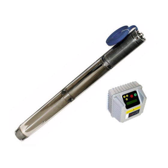
1. Introduction of the 4HS submersible pumps range 4HS is a 4” high speed centrifugal submersible pump for clean water composed by: high speed three phase asynchronous motor with wet rotor and canned type resin filled stator. Built-in inverter on board driven by a dedicated control module (CM) positioned outside the well. -
Page 4: Safety Instructions
Do not start the pump for any reason if not completely immersed in water. Avoid any shock or serious impact during transportation. Check the 4HS immediately upon delivery and check for damage and/or missing parts. In either case, immediately notify the supplier. -
Page 5: Packing Content
Pressure transducer Operating Manual Cable junction kit Check the 4HS packing immediately upon delivery and check for damage and/or missing parts; in either cases immediately notify the supplier 5. General technical features PUMP Max. temperature of pumped liquid 35 °C (92 °F) -
Page 6: Pump Installation
6. Pump installation Entire installation procedure must be performed verifying that pump is not connected to the mains. Pump can be installed both vertically and horizontally, but the outlet should never be below the horizontal line. If the pump is not installed in a well, to grant a proper cooling, a cooling sleeve must be used;... -
Page 7: Pump Cable
Ensure the pump in the well with a stainless steel rope to be fixed to the hole in the pump head 6.2 Pump cable 4HS are equipped, in their standard configuration, with 5 meter flat cable length. SINGLE PHASE INPUT POWER brown... -
Page 8: Cm Installation
To make the junction is necessary to follow carefully the instructions inside the kit. At the time of joining and electrical connection is essential to maintain the correspondence between the signal cables. After cable joining and placed the pump in the well you must perform, before connecting to the CM, a test of insulation: join together the two power cables and, applying a voltage of 500V, an insulation resistance from the ground higher than 100 Mohm must be verified. -
Page 9: Electric Wiring
7.1 Electric wiring Input power line (LINE): Output power line (PUMP): Pump signal: L1,L2 power line M1,M2 terminals S+ (red) GND ground GND ground S- (white) Analog inputs: Digital inputs: Communication Digital outputs (relays): ... -
Page 10: Hs Pumps Installation For Constant Pressure Mode
Otherwise, you may fail to connect to ground the cover with a risk of electric shock or even death. 8. 4HS pumps installation for constant pressure mode CM can manage the rotation speed of pump to maintain constant the pressure in a point of plant regardless the water demand of the user. -
Page 11: Pressure Tank
8.1 Pressure tank Installation of a pressure tank in the hydraulic system is recommended to compensate leakage of water in the system (or during minimum water demand) and to avoid continuous start/stop cycling of the pump (check the appendix for more information). Selecting the proper volume and pre-charge pressure of the tank is very important;... -
Page 12: Minimum Stop Frequency At 0 Delivery (F Min Q=0) During Constant Pressure Control
To stabilize the pressure control operated by the CM module, it is suggested to put the pressure sensor near the well exit, after the check valve. Pressure sensor and power cables can be close but it is suggested to use a shield cable connecting the shield to the sensor ground pin. -
Page 13: Hs Pumps Performance Range
9. 4HS pumps performance range... -
Page 16: Hs Use And Programming
Screen is a back-lit LCD displaying 2 rows of 16 digits each. Alarms are indicated by an audible signal. 10.2 Initial setting When the 4HS is switched on for the first time, the initial setting menu is displayed for the initial setting of parameters to configure pumps and plant characteristics. - Page 17 It is the pressure value to be kept constant. Set pressure p = XX.X [bar] If ON is selected, after a lack of voltage, 4HS returns to its Auto restart normal status; if 4HS was powering the pump before voltage drop, it returns to feed the pump without any kind of advise.
-
Page 18: Initial View
Inv:ON XXX.X Hz CM is powered and feeding the 4HS showing its frequency. Inv:ON Mot: OFF CM is powered but 4HS is not running (i.e. motor/pump was stopped due to minimum frequency being reached). Inv:OFF Mot: OFF 4HS is not controlled. -
Page 19: Menu Display
10.4 Menu display Pressing ENTER where you are in *MENU’ / ENT to access] in initial display, the following MENUs are displayed: MENU Password required to enter (default 001) Instal. param. MENU Password required to enter (default 002) Advanced param. MENU Installer password required to enter (default 001) It is possible to return to original default set parameters (Change Init. - Page 20 parameter desciption Pressure unit Unit bar/psi °C Temperature unit Unit °C / °F Maximum pressure of pressure transducer; Set the pressure value of the transducer F.s. press.sensor when output signal is 20 mA equivalent to the highest value of pressure range 20mA = XX.X [bar] (i.e.
- Page 21 parameter desciption The pressure value to be kept constant. Set pressure p = XX.X [bar] Pressure compensation at the maximum p loss compens. frequency for each pump. Acting on the green button you can reverse the sign. p = XX.X [bar] ...
- Page 22 parameter desciption Set the frequency value (or the speed) to feed Operating freq. the pump. f = XXX [Hz] Set the frequency value (or the speed) to feed Operating freq. 2 the pump. f = XXX [Hz] ...
- Page 23 parameter desciption It 's the increase of pressure respect to Delta stop press pressure set which must be passed so that there is a forced shutdown of the pump. p = XX.X [bar] The common parameters than you should get Delta start temp.
-
Page 24: Advanced Parameters
= XXX [Hz] Minimum frequency of the motor. Note: for 4HS pump Min motor freq. is not advisable to set minimum frequency lower than 40 Hz in order to protect the integrity of the thrust f = XXX [Hz] bearings. - Page 25 Dry run cosphi its lowest level. Typically the value 0.50 is sufficient to cosphi = X.XX detect dry running pump 4HS. Carrier frequency (switching frequency). It is possible to chose PWM in the range of 2.5 ,4, 8, 10, 12 kHz .
- Page 26 If ON is selected, after a lack of voltage, 4HS returns to Autorestart its normal status; if 4HS was powering the pump before voltage drop, it returns to feed the pump ON/OFF without any kind of advise.
-
Page 27: Protections And Alarms
11. Protections and alarms Anytime a protection occurs a blinking message is displayed together an acoustic alarm; on STATUS on INITIAL VIEW the protection is displayed; by pressing STOP button (only and exclusively from the this position of STATUS on INITIAL VIEW) is possible to try to reset the alarm;... - Page 28 ALARM MESSAGE ALARM DESCRIPTION POSSIBLE SOLUTION Measured pressure value Make sure about the possible causes to has reached the maximum reach the max pressure OVER PRESSURE pressure accepted by the Check the max pressure value set system Make sure about the possible causes to Measured pressure value reach the min pressure (i.e.
- Page 29 POSSIBLE SOLUTION If pumps cosphi is lower than the dry running cosphi for at least 2 seconds, CM stop the pump. 4HS try to run the pumps every 10, 20, 40, 80, 160 minutes and then the pump is definitely stopped.
-
Page 30: Trouble-Shooting Chart
. After turning off the 4HS is contactor therefore recommended to wait at least 1 minute before start the system. -
Page 31: Technical Assistance
4HS model LCD version (shown when CM is power INV version (shown when CM is power supplied) supplied) 4HS - / LCD = _.__ INV = _.__ Line voltage: ___ [V] Line Frequency: 50 Hz... - Page 32 DECLARATION OF CONFORMITY In according with: Machine Directive 2006/42/EC EMC Directive 2004/108/CE 4HS 02/04, 02/08, 04/03, 04/05, 06/02, 06/04 conform to the following regulations: EN 55011 Class A EN 60335-1, EN60335-2-41 Vicenza, 06/09/2011 Ing. Marco Nassuato Operation Manager...
- Page 33 NOTE Copyright NASTEC srl 2011 Nastec reserves the right to modify informations in this manual without any notice. Nastec srl, Via della Tecnica, 8, 36024, Mossano, Vicenza, Italy, Tel. +39 0444 886289, Fax +39 0444 776099, www.nastec.eu, info@nastec.eu...
Need help?
Do you have a question about the 4HS and is the answer not in the manual?
Questions and answers
Pump connection wiring diagram with colours of the wires
For the Nastec 4HS pump, the connection wiring diagram with wire colors is as follows:
Power Wires (Single Phase Input):
- Brown
- Red
- Blue
- White
- Ground (Green/Yellow)
Signal Wires:
- S+ (Red)
- S− (White)
- Ground (Green/Yellow)
AC Power Supply:
- L2/N: Black
- PE (Protective Earth): Yellow/Green
DC Power Supply:
- Negative: Black
- PE: Yellow/Green
Notes:
- Respect polarity where indicated.
- Signal cables should be kept separate from power cables to reduce interference.
This answer is automatically generated