Table of Contents
Advertisement
Quick Links
Advertisement
Table of Contents

Related Manuals for Nastec PILOT


Summary of Contents for Nastec PILOT
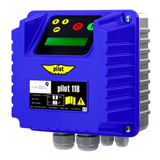
- Page 1 PILOT Installation, use and maintenance manual V 3.0 24/04/2022...
- Page 2 Copyright © Nastec srl The information contained in this document may be changed without notice Nastec srl, Via della Tecnica, 8, 36048, Barbarano Mossano, Vicenza, Italy, Tel. +39 0444 886289, Fax +39 0444 776099, info@nastec.eu, nastec.eu...
-
Page 3: Table Of Contents
PILOT Table of Contents 1. Introduction ............................4 1.1. Purpose of the manual ......................4 1.2. Product overview ........................4 2. Safety ..............................4 2.1. Symbols ..........................5 2.2. Qualified personnel ........................5 2.3. Safety warnings ........................5 2.4. Acoustic emission ........................7 2.5. -
Page 4: Introduction
• Dry run. PILOT provides an indication of the power factor (PF or cosø) and allows programming a minimum threshold relating to the dry run condition below which the pump is to be stopped. The device makes up to 5 automatic restart attempts with user-definable times. -
Page 5: Symbols
PILOT 2.1. Symbols This symbol indicates a TIP or recommendation. NOTE This symbol indicates a NOTE or an indication or concept to be emphasised. CAUTION This symbol indicates CAUTION, thus an indication which failure to respect can lead to minor or moderate damage. - Page 6 PILOT WARNING Before commissioning the product, ensure that the installation is safe and in accordance with local regulations. WARNING Comply with the provisions to meet EMC requirements. WARNING Use cables of the appropriate type and cross-section according to the electrical characteristics of the load, the ambient temperature and local regulations.
-
Page 7: Acoustic Emission
3.2. Warranty Nastec guarantees that the products accompanied by this warranty are free from material or workmanship defects. The Company has the right to inspect any product returned under warranty, and confirm that the product contains a material or workmanship defect. -
Page 8: Product Registration
If the warranty is applicable, Nastec will repair the device. Nastec is willing to refurbish the product upon offer. In the absence of a warranty, Nastec will make an offer to repair and/or refurbish the device. After 60 days from the offer, if no response is received from the buyer, Nastec will scrap the product upon notice. -
Page 9: Disposal
WARNING Failure to comply with the instructions may lead to loss of warranty. For more information contact the dealer or technical support at service@nastec.eu or by opening a support ticket on the portal service.nastec.eu 3.6. Disposal Devices marked with this symbol cannot be disposed of in household waste but must be disposed of at appropriate waste drop-off centres. -
Page 10: Storage
If the product is put back into storage after it has been used, it is advisable to contact the manufacturer for further information on storage. For more information contact the dealer or technical support at service@nastec.eu or by opening a support ticket on the portal service.nastec.eu 5. -
Page 11: Dimensions And Weight
Protect the device from direct exposure to weather and sunlight. 5.2. Dimensions and weight 180 mm 120 mm Model Maximum weight [kg] PILOT 112 1x230V PILOT 118 1x230V PILOT 312 3x230V PILOT 325 3x230V PILOT 330 3x230V PILOT 312 3x400V... -
Page 12: Cooling
PILOT WARNING Do not install the device in environments at a risk of explosion, flooding, or in the presence of flammable fluids or solids. Ensure sufficient ventilation in the room. Refer to local regulations when selecting the appropriate installation location. -
Page 13: Electrical Installation
[Nm] tightening torque cable with ground cable with ground PILOT 112 1x230V 3 x 6 mm 3x 6 mm PILOT 118 1x230V 3 x 6 mm 3 x 6 mm PILOT 312 3x230V... -
Page 14: Protection Devices
These trigger in the event of failure of a component inside the device. Supply voltage Model Recommended fuse Recommended circuit breaker ABB MCB S200 1 x 230 VAC PILOT 112 1x230V S201-C16 1 x 230 VAC PILOT 118 1x230V S201-C25 3 x 230 VAC PILOT 312 3x230V... -
Page 15: Power Connections
PILOT 7.4.1. Power connections PILOT 112 1x230V , PILOT 118 1x230V A [mm] Pre-insulated cable lug Stripping diagram Fork for M4 screw Power Supply Fork for M4 screw LINE Fork for M4 screw P.E. Fork for M4 screw Motor MAIN... - Page 16 PILOT PILOT 312 3x230V , PILOT 312 3x400V , PILOT 312 3x460V 13 NO A1 1 L1 3 L2 5 L3 2 T1 4 T2 6 T3 A [mm] Pre-insulated cable lug Stripping diagram Fork for M4 screw Power Supply...
-
Page 17: Control Connections
The circuit board AVIATOR allows increasing the starting torque of single-phase motors in a simple and economical way. AVIATORIt can be ordered as an accessory for PILOT 118 1x230V, is equipped with specific contacts with which it is mechanically and electrically coupled to the power board of the PILOT. The starting capacitor, present in the board AVIATOR, is inserted in parallel with the run capacitor only in the starting phase of the motor. - Page 18 PILOT Model Motor power [kW] Starting capacitor [µF] AVIATOR 1 0,37 - 0,55 53 - 6 4 AVIATOR 2 0,75 - 1,1 108 - 130 AVIATOR 3 1,5 - 2,2 1 8 9 - 2 27 Procedure for installing the board AVIATOR: Make the power connections relative to the power supply, the motor and the run capacitor (if present).
- Page 19 PILOT Place board AVIATOR above board PILOT. Insert the female faston terminals of board AVIATOR in the male faston terminals of board PILOT paying attention to the correct insertion of all 4 terminals. Gently press the board AVIATOR downwards making sure the faston contacts are correctly coupling.
-
Page 20: Commissioning
PILOT Check the correct and safe positioning of board AVIATOR on board PILOT. Close the cover. 8. Commissioning 8.1. Preliminary checks Before supplying power to the device, carry out the following electrical and mechanical checks: • Check that the device complies with the motor control according to its data plate. -
Page 21: Powering
PILOT • Check that the cable glands and screws are properly tightened. • Check that the device is completely closed and that live parts are not accessible. 8.2. Powering DANGER Before supplying power to the device, make sure you have read, understood and implemented all the safety, mechanical, and electrical installation instructions. -
Page 22: Diagnostics
PILOT Parameter Description P.F = X.XX The P.F. parameter represents the measured power factor (cosØ). STATUS: NORMAL In the absence of alarms, the STATUS is NORMAL. Otherwise, the alarm message flashes. Press th ENTER key to access the Diagnostics menu. -
Page 23: Alarms
PILOT 10. Alarms When an alarm occurs, the device starts emitting an acoustic signal (if available) and an intermittent warning ap- pears on the STATUS screen indicating the corresponding alarm. By pressing the STOP key (only and exclusively in correspondence with the STATUS screen) it is possible to attempt to reset the machine. If the cause of the alarm has not been resolved, the device displays the alarm again and emits an acoustic signal. - Page 24 PILOT NOTE The correct value for parameter Dry run PF depends on: • The type of motor (construction and winding data). Generally, three-phase surface motors have a higher rated cosphi than submersible motors having the same power rating. • The type of pump (hydraulic performance and power consumption curve).
-
Page 25: Ec Declaration Of Conformity
PILOT 12. EC Declaration of Conformity The manufacturer hereby: Nastec srl Via della Tecnica, 8, 36048, Barbarano Mossano, Vicenza, Italy declares under its own responsibility that the product: PILOT complies with the following directives: • 2011/65 / EU - RoHS Directive •... -
Page 26: Declaration Of Conformity
PILOT 13. UK Declaration of Conformity The manufacturer hereby: Nastec srl Via della Tecnica, 8, 36048, Barbarano Mossano, Vicenza, Italy declares, under its own responsibility, that the product: PILOT complies with the following directives: • UK SI 2012 No. 3032. Restriction of the Use of Certain Hazardous Substances in Electrical and Electronic Equipment Regulations 2012 (RoHS2) •...
Need help?
Do you have a question about the PILOT and is the answer not in the manual?
Questions and answers