Table of Contents
Advertisement
Quick Links
Installation
Manual
Automatic & Non-Automatic Transfer & Bypass-Isolation Switches
DANGER is used in this manual to warn of a
hazard situation which, if not avoided, will result in
death or serious injury.
WARNING is used in this manual to warn of a
hazardous situation which, if not avoided, could
result death or serious injury.
CAUTION is used in this manual to warn of a
hazardous situation which, if not avoided, could
result in minor or moderate injury.
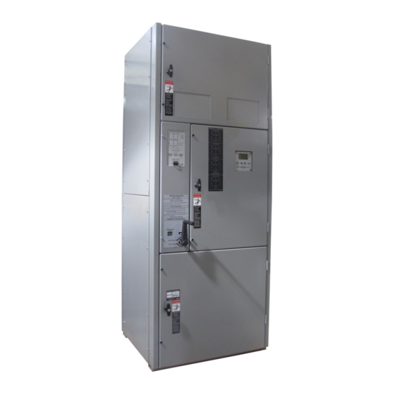
4000 Series, J-Design 150-600 A
Electrically-operated bypass switch with Bypass-Isolation & Group H controllers
Refer to the outline and wiring drawings provided with
the 4000 Series transfer switch for all installation and
connection details and accessories.
Refer to User's Guide 381333-444 for the Group H
Controller status display messages, time delays, pickup
and dropout settings, and adjustments.
Rating Label
Each transfer switch contains a rating label to define the loads
and fault circuit withstand/closing ratings. Refer to the label
on the transfer switch for specific values.
Do not exceed the values on the rating label.
Exceeding the rating can cause person injury or
serious equipment damage.
An experienced licensed electrician must install the switch.
Table of Contents
Nameplate ....................................................................... 2
Catalog Number Identification ........................................ 2
INSTALLATION .................................................. 3-4
Line Connections, Auxiliary Circuits ............................... 3
Engine Starting Contacts ................................................ 4
FUNCTIONAL TEST ........................................... 5-6
1- Voltage Checks........................................................... 5
2- Electrical Operation .................................................... 6
BYPASSING & ISOLATING ............................. 8-15
Bypassing the ATS ......................................................... 8
Isolating the ATS ............................................................. 9
Contact Inspection ........................................................ 11
Return to Operation ...................................................... 12
Unbypassing ................................................................. 14
Manual Load Transfer ................................................... 15
TESTING & SERVICE ..................................... 16-17
Replacement Parts, Yearly Inspection.......................... 16
Maintenance Handle ..................................................... 17
Troubleshooting ....................................................... 18-19
INDEX ........................................................................... 20
381333-445 B
Advertisement
Table of Contents

Related Manuals for Asco J 4000 Series


Summary of Contents for Asco J 4000 Series
-
Page 1: Table Of Contents
Installation 4000 Series, J-Design 150-600 A Manual Automatic & Non-Automatic Transfer & Bypass-Isolation Switches Electrically-operated bypass switch with Bypass-Isolation & Group H controllers Refer to the outline and wiring drawings provided with the 4000 Series transfer switch for all installation and connection details and accessories. -
Page 2: Nameplate
ASCO 4ATE, 4ACTE, 4ADTE, 4NTE, 4NCTE, 4NDTE Installation Manual Nameplate Catalog Number Identification The nameplate includes data for each specific 4000 Series Typical 4000 Series J4ATE catalog no. for switched neutral, 3 transfer switch. Use the switch only within the limits shown on pole, 400 ampere, 480 V, ATE in Type I enclosure: this nameplate. -
Page 3: Installation
Installation Manual 381333-445 ASCO 4ATE, 4ACTE, 4ADTE, 4NTE, 4NCTE, 4NDTE Installation Line Connections Refer to the wiring diagram provided with the transfer switch. These transfer switches are factory wired and tested. All wiring must be made in accordance with the National Installation requires mounting, connecting power cables, and Electrical Code and local codes. -
Page 4: Engine Starting Contacts
ASCO 4ATE, 4ACTE, 4ADTE, 4NTE, 4NCTE, 4NDTE Installation Manual Engine Starting Contacts All customer connections, including the engine control contact connections, are located on terminal block TB which is mounted on the top right side of the enclosure. Refer to the wiring diagram provided with this switch and connect the engine start wires to the appropriate terminal. -
Page 5: Functional Test
Installation Manual 381333-445 ASCO 4ATE, 4ACTE, 4ADTE, 4NTE, 4NCTE, 4NDTE Functional Test The Functional Test consists of two checks: voltage checks and electrical operation. Read all instructions on the wiring diagram and labels affixed Use extreme caution when using a meter to to the transfer switch. -
Page 6: 2- Electrical Operation
ASCO 4ATE, 4ACTE, 4ADTE, 4NTE, 4NCTE, 4NDTE Installation Manual The normal source must be available and the generator must be ready to start. Check that the normal source accepted light is on. Press the transfer button. The engine should start and run within 15 seconds. -
Page 7: Bypassing & Isolating
Installation Manual 381333-445 ASCO 4ATE, 4ACTE, 4ADTE, 4NTE, 4NCTE, 4NDTE Bypassing & Isolating The Bypass Switch (electrically-operated) is controlled by a bypass-isolation controller (Figure 4). It provides status lights and push-button operation of the Bypass Switch. Bypass & Isolation Status... -
Page 8: Bypassing The Ats
ASCO 4ATE, 4ACTE, 4ADTE, 4NTE, 4NCTE, 4NDTE Installation Manual Bypassing & Isolating continued Bypassing the ATS This procedure explains how to bypass the closed transfer switch contacts. Bypassing is required before the Transfer Switch can be tested or isolated. The Bypassed lights must be off and the Connected light must be on. See Figure 4. -
Page 9: Isolating The Ats
Installation Manual 381333-445 ASCO 4ATE, 4ACTE, 4ADTE, 4NTE, 4NCTE, 4NDTE Isolating the ATS (to TEST Positon) Isolating is required before any service work can be performed on the automatic transfer switch. Refer to Figures 11-16. NOTE: Bypass Switch can be used for manual load transfer to an available power source if transfer switch is in the TEST or ISOLATE position. - Page 10 ASCO 4ATE, 4ACTE, 4ADTE, 4NTE, 4NCTE, 4NDTE Installation Manual Isolating the ATS (to ISOLATE Positon) continued Hazardous voltage capable of causing shock, burns, or death is used in this transfer switch. Do not touch any control circuit terminals. 3. Continue turning the Connection / Isolation Handle counterclockwise (approximately 5-6 turns) until window shows ISOLATE.
-
Page 11: Contact Inspection
Installation Manual 381333-445 ASCO 4ATE, 4ACTE, 4ADTE, 4NTE, 4NCTE, 4NDTE 4. Open the lower enclosure door. Pull out both left and right side rails then use the two tab handles to roll out the transfer switch. It can be safely inspected in this position. -
Page 12: Return To Operation
ASCO 4ATE, 4ACTE, 4ADTE, 4NTE, 4NCTE, 4NDTE Installation Manual Return to Operation This procedure explains how to return the automatic transfer switch (ATS) to operation after inspection and maintenance. 1. Use the two tab handles to roll the transfer switch into the enclosure (isolation contacts facing inward) until the crank bearings stop against the draw-in plates. - Page 13 Installation Manual 381333-445 ASCO 4ATE, 4ACTE, 4ADTE, 4NTE, 4NCTE, 4NDTE 4. Observe which Bypassed To light is on (Normal or Emergency). This indicates the source connected to the load. 5. Observe which ATS On light is on (Normal or Emergency).
-
Page 14: Unbypassing
ASCO 4ATE, 4ACTE, 4ADTE, 4NTE, 4NCTE, 4NDTE Installation Manual Unbypass ATS is connected to Emergency Source ATS is connected to Normal Source 1. Press and hold the Unbypass button until the Bypassed 1. Press and hold the Unbypass button until the Bypassed to Emergency light goes off. -
Page 15: Manual Load Transfer
Installation Manual 381333-445 ASCO 4ATE, 4ACTE, 4ADTE, 4NTE, 4NCTE, 4NDTE Manual Load Transfer This emergency procedure uses the electrically-operated Bypass Switch to transfer the load to the other source (if available). It only can be used if the ATS is bypassed and isolated (racked out). The generator must be started via the Engine Control switch. -
Page 16: Testing & Service
The panel will sources, then remove the transfer switch barriers and check the revert to normal operation after 30 seconds. An ASCO contact condition. The non-replaceable main contacts are Services technician uses this button for diagnostics. -
Page 17: Maintenance Handle
Installation Manual 381333-445 ASCO 4ATE, 4ACTE, 4ADTE, 4NTE, 4NCTE, 4NDTE Testing & Service Maintenance Handle 1. Bypass, isolate, and withdraw the transfer switch (pages 7- 11). Then locate and remove the maintenance handle from the storage location (inside lower left side). Insert the handle into the hole in the molded hub on the left side of the operator of the transfer switch. -
Page 18: Troubleshooting
ASCO 4ATE, 4ACTE, 4ADTE, 4NTE, 4NCTE, 4NDTE Installation Manual Troubleshooting Check in Numerical Sequence 1 Operation 2 Generator 3 Voltage For 4ATE, 4ACTE, 4ADTE the Starting control must be in The outage must be long engine-generator set does not start automatic position. - Page 19 Installation Manual 381333-445 ASCO 4ATE, 4ACTE, 4ADTE, 4NTE, 4NCTE, 4NDTE Troubleshooting (continued) Check in Numerical Sequence Problem 1 Check 2 Solution 3 See Page The Bypass to Normal button Is the Permitted light on You can only bypass the closed...
-
Page 20: Index
ASCO 4ATE, 4ACTE, 4ADTE, 4NTE, 4NCTE, 4NDTE Installation Manual INDEX Alarm light, 7, 19 Handle, Connection / Isolation, permitted light, 7, 19 ASCO Services Inc. 2, 9, 10, 12, 13 phase rotation, 3, 5 800-800-2726(ASCO) HELP 800-800-2726(ASCO) preventive maintenance, 16 customercare@ascopower.com...
Need help?
Do you have a question about the J 4000 Series and is the answer not in the manual?
Questions and answers