Advertisement
Quick Links
Advertisement

Related Manuals for Bentel Security Academy8L


Summary of Contents for Bentel Security Academy8L
- Page 2 Installation of the control panel must carried out strictly according to the instructions, and in compliance with the safety laws in force. BENTEL SECURITY srl reserves the right to modify the technical specifications of this product without prior notice. via Florida - Z.I. Valtesino - 63013 GROTTAMMARE (AP) - ITALY...
-
Page 3: Table Of Contents
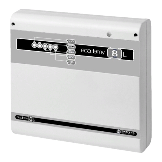
TABLE OF CONTENTS PARTS The Main Unit ..... . . 5 INSTALLATION Mounting the Panel ....6 Terminal board . - Page 4 Figure 1 Parts Security System Control Panel Academy8L...
- Page 5 PARTS The table below provides a brief description of each part (the numbers in boldface refer to the parts illustrated in the figure 1), and the meaning of the ON / OFF status of each indicator LED. PARTS DESCRIPTIONS 1 4 screws 2 5 Indicator LEDs 3 4 holes (Ø...
-
Page 6: Installation
The V column shows the voltage on the corresponding terminal. The I column shows the maximum current for each terminal. Where (1) or (2) is shown as the value in the I column refer to the footnote below the terminal description table. Security System Control Panel Academy8L... -
Page 7: Power Supply Connection
Terminal DESCRIPTION 5-8-11-14 Sensor power-supply terminals 13.8 17-20-23-26 [+F] 6-9-12-15-18 Alarm Zones programmable as NC, NO, Balanced or 21-24-27 [L1… … L8] Double Balanced 7-10-13-16-19-22 Ground and Negative 25-28-30-36 [ Power supply to additional devices (keypads and key 1 [+] 13.8 readers) Connection terminal for standard BPI control devices... -
Page 8: Open Panel
Access the programming phase before opening the Panel for servicing, testing etc., as this will disable the Tamper microswitch. Step 1 Enter INSTALLER PIN. Step 2 Press to access programming. Step 3 Open the Panel. Step 1 Enter MAIN USER PIN. Step 2 Press Security System Control Panel Academy8L... -
Page 9: A Typical System
Step 3 Press to access programming. Step 4 Open the Panel and service as required. The OPEN LED on the keypads will stay ON until the Panel is closed again. No alarms will be generated during this phase. Step 5 Close the Panel. - Page 10 Figure 2 A Typical System...
- Page 11 INSTALLATION...
-
Page 12: Ncduevox Voice Board
NCDUEVOX voice board How to attach the NCDUEVOX voice board Disconnect the Mains and battery before attaching the NCDUEVOX board to a Panel that is in service. Step 1 Slot the NCDUEVOX voice board into its holder----microphone to the top. Step 2 Connect the NCDUEVOX cable (40) to the connector (4) on the Main Unit board.
Need help?
Do you have a question about the Academy8L and is the answer not in the manual?
Questions and answers